
Related Manuals for Unicont SPb DAC-109

Summary of Contents for Unicont SPb DAC-109
- Page 1 Unicont SPb Ltd Digital-Analogue Converter DAC-109 Technical Documentation (109-10-23032012) St. Petersburg 2012...
-
Page 2: Table Of Contents
Unicont SPb Ltd Technical Documentation DAC-109 Table of Contents PURPOSE ..........................3 DELIVERY SET .......................3 SPECIFICATIONS ......................3 INSTALLATION AND CONNECTION OF THE CONVERTER ......5 VOLTAGE SELECTION ....................10 PRINCIPLE OF CONVERTER OPERATION ............13 ... -
Page 3: Purpose
NMEA, into the synchro or step signals which are necessary for controlling analogue repeaters and other devices based on synchro or step repeaters. In addition, the converter DAC-109 may be used as a digital repeater for displaying a current value of course. - Page 4 Unicont SPb Ltd Technical Documentation DAC-109 Characteristics of the Remote Control Interface: Type of Interface: RS-232/422/485 Number of inputs/outputs: Speed of data receive/transmit: 9600 Bd Number of stop bits: Parity: Characteristics of LCD: Type of display: Character (16 characters x 2 lines)
-
Page 5: Installation And Connection Of The Converter
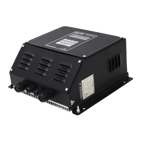
(see section 7). j) Check workability of the converter. Warning! If you want to connect ADPC-101 to DAC-109 you shall use special filter FDA-122. Otherwise ADPC-101 will not recognize synchro signal. - Page 6 Unicont SPb Ltd Technical Documentation DAC-109 Figure 1. Outline drawing of the converter. Page 6...
- Page 7 Unicont SPb Ltd Technical Documentation DAC-109 Figure 2. DAC-109 connection flowchart. The diagrams of connection of external devices and Synchro or Step consumers to DAC-109 IN_18-32V RELAY_NO CH_Switch IN_1 (NMEA) IN_2 (NMEA) REMOTE_OUT REMOTE_IN U ref U fase Main Backup...
- Page 8 Switching (AU-106) Positive Source Source Unit Fuse Power on/off IN 18-32 V 18..32 VDC Figure 4. The diagram of step consumers connection to DAC-109 with "common plus" IN_18-32V RELAY_NO CH_Switch IN_1 (NMEA) IN_2 (NMEA) REMOTE_OUT REMOTE_IN U ref U fase...
- Page 9 Unicont SPb Ltd Technical Documentation DAC-109 Figure 6. DAC-109 block-diagram. Figure 7. Connection diagram of interfaces RS-232 and RS-422/485 Page 9...
-
Page 10: Voltage Selection
Unicont SPb Ltd Technical Documentation DAC-109 5. VOLTAGE SELECTION The output voltage for the phase and reference channels may be selected by two methods: 1. By the connection of the wires to terminal block P12 and position of a wire link in terminal block P21. - Page 11 Unicont SPb Ltd Technical Documentation DAC-109 Positions of terminal blocks P12 and P21 on the PCB: Warning! Producers doesn’t connect wires to the P12 and user shall connect them! Wiring diagrams for different levels of output voltages: Table 1. The choose of synchro peripheries voltage level.
- Page 12 Unicont SPb Ltd Technical Documentation DAC-109 Ref. 75~110 VAC Phase 0~35 VAC Ref. 0~35 VAC Phase 35~75 VAC Ref. 35~75 VAC Phase 35~75 VAC Wires Ref. 75~110 VAC Phase 35~75 VAC Wires Ref. 0~35 VAC Phase 75~110 VAC Ref. 35~75 VAC Phase 75~110 VAC Ref.
-
Page 13: Principle Of Converter Operation
6. PRINCIPLE OF CONVERTER OPERATION 6.1 Standby Mode of the Converter Right after power-up the converter DAC-109 switches to the standby mode. Two course values are displayed at the display in this mode: 1. Accepted value of course from the NMEA source (e.g. digital gyrocompass) 2. - Page 14 When pressing the key [F3] in the standby mode of the converter (see par. 6.1) the configuration menu appears at the display of DAC-109: Exit from this menu to the standby mode of the converter is performed by the key [F3] (the set configurations are stored).
- Page 15 Unicont SPb Ltd Technical Documentation DAC-109 Ratio Choice Selection of the relation between the ship’s turn and the analogue receiver synchro’s turn. Available relations: 1:36, 1:60, 1:90, 1:180, 1:240, 1:360 Channel Select Selection of the main channel for receiving data about a course in the digital sentences NMEA 0183.
- Page 16 Available values of this parameter are: 2, 3, 4, 5, 6, 7, 8, 9, 10 sec. 6.3 Alarm System Several types of warning are foreseen in the DAC-109: absence of data at the main channel, absence of data at the reserve channel, absence of data at the main and reserve channel, absence of connection to the synchro-receiver, the initial position of connected analogue repeaters are not entered (see par.6.4).
- Page 17 Warning about Absence of Data at the Reserve Channel If the setting «Backup channel» is set in «ON», DAC-109 controls receiving of data through the reserve channel. When data at the reserve channel is missing, the mark «!» appears at the indicator in the upper line, on the right from the value of course, accepted through the main channel.
-
Page 18: Debug Tools And Diagnostic Aids
7. DEBUG TOOLS AND DIAGNOSTIC AIDS 7.1 Imitation of Digital Gyrocompass In order to simplify the process of setting the converter and connected repeaters, DAC-109 is provided with a special mode of imitation the digital gyrocompass. In this mode the converter ignores accepted data about the course from the sources of signal NMEA 0183 and processes the values of course, entered by the user from the converter’s keyboard. - Page 19 The second mode which is necessary for simple debugging the connected repeaters – is the imitation of cyclical turn of the ship. In this mode DAC-109 emulates a constant turn of the ship to the right with the speed of 360°/min. Changing of course at the connected repeaters, if they are connected properly, should occur with a constant speed without jerks or wobble and without changing the rotational direction.
-
Page 20: Typical Defects And Methods Of Troubleshooting
Technical Documentation DAC-109 8. TYPICAL DEFECTS AND METHODS OF TROUBLESHOOTING Faulty condition of DAC-109 can be caused by mechanical or electrical damage. Some malfunctions and methods for their elimination are listed in the table below (Table 3). Table 3 Typical malfunctions and methods of troubleshooting. - Page 21 Unicont SPb Ltd Technical Documentation DAC-109 Short-circuit in the load Eliminate the cause of short circuit circuit Check the connections of repeaters and control lines. (See The load parameters exceed The translator display item in this table, “The number the maximum allowable...
-
Page 22: Warranty
Technical Documentation DAC-109 9. WARRANTY The manufacturer guarantees the unit DAC-109 complies with this manual provided that the operation, transportation and storage conditions are adhered to during the warranty period. The unit’s warranty period expires 24 months from the date of its shipping from the manufacturer’s storehouse. -
Page 23: Date Of Packing
Unicont SPb Ltd Technical Documentation DAC-109 10. DATE OF PACKING Digital-Analogue Converter DAC-109 № name of article designation serial number Packed Unicont SPb Ltd., Russia. Manufacturer according to the requirements of the current technical documentation. post signature clarification of signature year, month, day 11.
Need help?
Do you have a question about the DAC-109 and is the answer not in the manual?
Questions and answers