Table of Contents
Advertisement
Available languages
Available languages
Manual de Usuario / User's Manual
ceiling series
Antes de utilizar el equipo, lea la sección
"Precauciones de seguridad" de este manual.
Conserve este manual para futuras consultas.
Before operating the device, please read the
"Safety precautions" section of this manual.
Retain this manual for future reference.
Advertisement
Chapters
Table of Contents

Related Manuals for D.A.S. CL-5


Summary of Contents for D.A.S. CL-5
- Page 1 Manual de Usuario / User’s Manual ceiling series Antes de utilizar el equipo, lea la sección “Precauciones de seguridad” de este manual. Conserve este manual para futuras consultas. Before operating the device, please read the “Safety precautions” section of this manual. Retain this manual for future reference.
- Page 2 ceiling...
- Page 3 Ceiling Series Ceiling Series Precauciones de Seguridad Precauciones de Seguridad Safety Precautions Safety Precautions Altavoces de techo / Ceiling loudspeakers Altavoces de techo / Ceiling loudspeakers El signo de exclamación dentro de un triángulo indica la existencia The exclamation point inside an equilateral triangle is intend to alert de importantes instrucciones de operación y mantenimiento en la the users to the presence of important operating and maintenance documentación que acompaña al producto.
- Page 4 GARANTÍA Todos nuestros productos están garantizados por un periodo de 24 meses desde la fecha de compra. Las garantías sólo serán válidas si son por un defecto de fabricación y en ningún caso por un uso incorrecto del producto. reparaciones garantía pueden realizadas,...
-
Page 5: Declaration Of Conformity
DECLARACIÓN DE CONFORMIDAD DECLARATION OF CONFORMITY D.A.S. AUDIO, S.A. C/ Islas Baleares, 24 - 46988 - Pol. Fuente del Jarro - Valencia. España (Spain). Declara que la serie Ceiling Loudspeakers: Declares as it’s sole responsibility that Ceiling Loudspeakers series: Cumple con los objetivos esenciales de las Directivas: Abide by essential objectives relating Directives: Directiva de Baja Tensión (Low Voltage Directive) 2006/95/CE... - Page 6 Manual del Usuario / Ceiling Loudspeakers User’s Manual...
-
Page 7: Table Of Contents
ÍNDICE INTRODUCCIÓN Generalidades Características Descripción INSTALACIÓN Consideraciones previas.Tipos de instalación Instalación AMPLIFICADORES DAS A EMPLEAR MANTENIMIENTO. PRECAUCIONES Manual del Usuario / Ceiling Loudspeakers User’s Manual... - Page 8 Manual del Usuario / Ceiling Loudspeakers User’s Manual...
-
Page 9: Introducción
• La serie consta de siete modelos: CL-5, CL-6, CL-8, CL- • Cada modelo se compone de tres partes esenciales: el 5T, CL-6T, CL-8T y CL-6TB. -
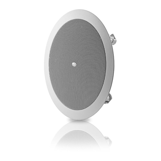
Page 10: Descripción
1.3 Descripción Se presenta un gráfico con los tres modelos básicos de la serie de altavoces de techo de D.A.S. Audio: Figura 2 – vista trasera CL-5 2. INSTALACIÓN 2.1 Consideraciones previas. Tipos de instalación Para la completa instalación del producto, es necesario prever tanto la realización de orificios circulares en los lugares... -
Page 11: Instalación
DIÁMETRO DIÁMETRO PARA situadas por canal. Se evitará así, trabajar en saturación y necesaria INTERNO ORIFICIO provocar rotura de los altavoces. CL-5, CL-5T 70mm CL-6, CL-6T 80mm Por ejemplo, para el caso de la instalación anterior CL-8, CL-8T 97mm suponiendo que se está empleando el modelo CL-6 de 40W... - Page 12 Tercer paso - Conexión de terminales: realizar la conexión entre los terminales de los cables con las bornas de presión del altavoz, cuidando mantener correctamente la polaridad. Para insertar los cables en las bornas, presione éstas para que quede accesible el orificio donde insertar el terminal; una vez hecho esto deje de hacer presión y el cable habrá...
-
Page 13: Amplificadores Das A Emplear
Sexto paso - Colocar de nuevo la reja: una vez apretados En la práctica se tiende a saturar un amplificador de potencia los tornillos el sistema ha quedado fijado al techo, tan solo insuficiente porque no nos entrega el nivel que esperamos. resta insertar la reja en su encaje correspondiente. - Page 14 Manual del Usuario / Ceiling Loudspeakers User’s Manual...
- Page 15 CONTENTS INTRODUCTION General Features Description INSTALLATION Preliminary considerations. Types of installation Installation DAS AMPLIFIERS TO BE USED MAINTENANCE. USE Manual del Usuario / Ceiling Loudspeakers User’s Manual...
- Page 16 Manual del Usuario / Ceiling Loudspeakers User’s Manual...
-
Page 17: Introduction
• Polypropylene cones avoid age deterioration when exposed to heat and air humidity. • The series comprises seven models: CL-5, CL-6, CL-8, CL-5T, CL-6T, CL-8T and CL-6TB. • Technical specs are shown below for the basic models: MODEL Nominal... -
Page 18: Description
1.3 Description The three basic models of the series can be seen below: Fig. 2 –CL-5, back view 2. INSTALLATION 2.1 Preliminary considerations. Types of installation For complete installation, we need to take the time to plan ahead the cutting out tile holes and the cabling of the units. -
Page 19: Installation
Similarly, if one does not wish to use a transformer model, the 2.2 Installation number of units in series-parallel can be increased, as long as 4 or more ohms impedance is achieved, as follows. The different installation steps are described. Before this can take place, the installation should be wired, leaving all of the Each amplifier will drive two loads in parallel. - Page 20 Step 5 – Screwing and fixing: to fix the assembly to the ceiling, the tabs have to be rotated and lowered. This is done by tightening the corresponding screws clockwise. The first quarter turn rotates the tab into position and out of the guide; the rest tightens the tab down onto the back of the ceiling surface.
-
Page 21: Das Amplifiers To Be Used
3. DAS AMPLIFIERS TO BE USED For model CL-5T installations, some DAS Audio amplifiers provide 70 and 100V outputs. Model Line Mode Power E-12 Stereo E-20 Stereo E-12 Bridge 1220 To calculate the required amplifier power for a 70 or 100V line, simply sum the input power selection of all speakers connected to a given amplifier channel. - Page 22 Manual del Usuario / Ceiling Loudspeakers User’s Manual...
- Page 24 www.dasaudio.com D.A.S. AUDIO, S.A. D.A.S. AUDIO OF AMERICA, INC. D.A.S. AUDIO ASIA PTE. LTD. C/. Islas Baleares, 24 Sunset Palmetto Park 25 Kaki Bukit Crescent #01-00/02-00 46988 Fuente del Jarro 6816 NW 77th Court. Kaki Bukit Techpark 1 Valencia, SPAIN Miami, FL.
Need help?
Do you have a question about the CL-5 and is the answer not in the manual?
Questions and answers