Table of Contents
Advertisement
Advertisement
Table of Contents

Related Manuals for D.A.S. reference rf-12.85


Summary of Contents for D.A.S. reference rf-12.85
- Page 1 User’s Manual reference series Antes de utilizar el equipo, lea la sección “Precauciones de seguridad” de este manual. Conserve este manual para futuras consultas. Before operating the device, please read the “Safety precautions” section of this manual. Retain this manual for future reference.
- Page 3 TRD-2 trípode modelo con pies a su máxima extensión es: with legs fully open: Rf-12.85 Rf-12.85 ------------->115 cm ------------->115 cm Rf-15.85 Rf-15.85 ------------->105 cm ------------->105 cm...
- Page 4 GARANTÍA Todos nuestros productos están garantizados por un periodo de 24 meses desde la fecha de compra. Las garantías sólo serán válidas si son por un defecto de fabricación y en ningún caso por un uso incorrecto del producto. reparaciones garantía pueden realizadas,...
- Page 5 DECLARACIÓN DE CONFORMIDAD DECLARATION OF CONFORMITY D.A.S. Audio, S.A. C/ Islas Baleares, 24 - 46988 - Pol. Fuente del Jarro - Valencia. España (Spain). serie reference Declara que la reference series Declares that Cumple con los objetivos esenciales de las Directivas: Abide by essential objectives relating Directives: Directiva de Baja Tensión (Low Voltage Directive) 2006/95/CE...
- Page 6 Manual del Usuario / r eference / User’s Manual...
-
Page 7: Table Of Contents
CONTENTS INTRODUCTION General Features Model’s features CONNECTIONS Wiring Basic connection PLACEMENT AND MOUNTING Placement Tripod use sub-18H TRD-4 Use on with Rotating the horns Weather resistance RIGGING Warnings Introduction Flying with ANL-2 Rigging with AX-TRUSS Rigging with AXA Rigging with AXU CONFIGURATIONS LINE DRAWINGS SPECIFICATIONS... - Page 8 Manual del Usuario / r eference / User’s Manual...
-
Page 9: Introduction
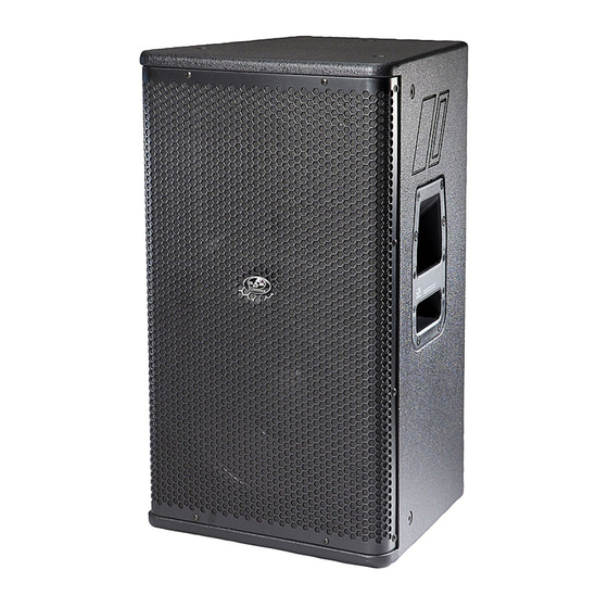
INTRODUCTION General Model’s features Rf-12.85 Thank you for purchasing a D.A.S. product. reference series represents more than 30 years - Two-way full-range system. of expertise in transducer and enclosure design, - Trapezoidal enclosure. achieving a series of systems that utilize the most - Tripod socket. - Page 10 Rf-12.64 sub-18H - Two-way full-range system. - Sub-woofer system. - Trapezoidal enclosure. - Rectangular enclosure. - Tripod socket. - Tripod socket for mid-high enclosures. - 1 x 18" woofer; 4” voice coil diameter. - Passive (full-range) use. - Medium power. - 1 x 12"...
-
Page 11: Connections
It will number of speakers in parallel is equal to the then lock into place and be ready for use. impedance of one divided by the number of Rf-12.85 speakers. For instance, two in parallel The drawing illustrates the terminal total 4 ohms (8 ohms divided by 2 boxes equal 4). -
Page 12: Basic Connection
- Use the eight ohm table when connecting a Avoid series or series-parallel wiring schemes Rf series single eight ohm speaker per channel. For products, since they degrade sound Rf-15.85 instance, one in each channel of a stereo quality and thus we do not recommend them for amplifier or the high frequency band of an applications other than background music, paging, 215.96... - Page 13 When using the system in active (bi-amplified) DSP-26 mode, use the D.A.S. electronic processor or a 24 dB/octave electronic crossover Figures show the block diagram and basic set- Rf-12.85 Rf-15.85 Rf-12.64 unit with the crossover frequency set to 1800 Hz. up for models "HIGH" (+1, -1) (+1, -1) "HIGH"...
- Page 14 (+2, -2) (+2, -2) X-over "HIGH" "BASS" (+1, -1) (+1, -1) Active (bi-amp) operation sub-18H Figures show the block diagram and basic set- sub-18H up. The is a bass unit for active systems, so an electronic crossover will be required with a crossover frequency set in the range from 80 to 125 Hz.
-
Page 15: Placement And Mounting
PLACEMENT AND MOUNTING Rotating the horns Rf-12.85 Rf-15.85 Rf-12.64 Rf-15.64 Placement Models have rotatable horns. This allows maintaining Place the speakers ahead of the microphones. the original horn characteristics (wider horizontal Feedback (howling) occurs when the microphones coverage than vertical) when mounted in pick up the sound that comes out of the speakers horizontal position. -
Page 16: Rigging
RIGGING Absolutely no risks should be taken with regards to public safety. When flying enclosures Warnings from ceiling support structures, extreme care This manual contains needed information for should be taken to assure the load bearing flying D.A.S. Audio line array systems, description capabilities of the structures so that the installation of the elements and safety precautions. -
Page 17: Rigging With Ax-Truss
The following illustrations show different views Flying with eyebolts on eyebolt flying for a single box. The length of the back cables or chains determines the vertical The Allen-head screws must be removed and angle of the box. replaced by M10 eyebolts on one side of the enclosure. - Page 18 AX-TRUSS In order to attach the to the box, Once the rear side screw has been removed, AX-TRUSS firstly the screw on the upper rear side must be the base of the will be placed on the backed out a few turns (1). Then the rear side corner, making sure that the head of the upper screw must be completely removed (2).
-
Page 19: Rigging With Axa
Rigging with AXA AX-2RF12 / AX-2RF15 Array Frame. Mounting instructions. 1.- Flip the speakers upside down. Remove the existing speaker screws and rubber feet. Replace the screws used to attach the rubber feet to keep air from escaping. 2.- Position the speakers in the desired splay angle. - Page 20 AX-2RF12V / AX-2RF15V Array Frame. Mounting instructions. 1.- Flip the speakers upside down. Remove the existing speaker screws and rubber feet. Replace the screws used to attach the rubber feet to keep air from escaping. 2.- Position the speakers in the desired splay angle.
- Page 21 AX-2RF12 / AX-2RF15 Array Frame. Mounting instructions. 1.- Flip the speakers upside down. Remove the existing speaker screws and rubber feet. Replace the screws used to attach the rubber feet to keep air from escaping. 2.- Position the speakers in the desired splay angle.
-
Page 22: Rigging With Axu
Rigging with AXU AXU-RF12 is a wall mount accessory which is fixed to the internal metal structure included inside Rf-12.64 / Rf-12.85 By means of this accessory the unit can be fixed both vertically and horizontally. For Rf-15.64 / Rf-15.85 cabients, the AXU-RF15. -
Page 23: Configurations
CONFIGURATIONS 2xRf-12.85 2xRf-12.85 INPUT INPUT ±1 MF/HF ±1 MF/HF INPUT INPUT ±1 MF/HF ±1 MF/HF DSP-26 processor INPUT INPUT ±1 LF ±1 LF INPUT INPUT ±1 LF ±1 LF 2xsub-18H 2xsub-18H Recommended, 1000 W LF AMPLIFIER per channel @ 4 Ohms Recommended, 750 W MF/HF AMPLIFIER per channel @ 4 Ohms... - Page 24 2xRf-15.64 2xRf-15.64 INPUT INPUT ±1±2 MF/HF ±1±2 MF/HF INPUT INPUT ±1±2 MF/HF ±1±2 MF/HF DSP-26 processor INPUT INPUT ±1 LF ±1 LF INPUT INPUT ±1 LF ±1 LF 2xsub-218G 2xsub-218G Recommended, 1400 W LF AMPLIFIER per channel @ 4 Ohms Recommended, 750 W MF AMPLIFIER per channel @ 4 Ohms...
-
Page 25: Line Drawings
LINE DRAWINGS ALL DIMENSIONS IN MILIMETERS WARNING! DO NOT SUSPEND FROM THIS HANDLE WARNING! DO NOT SUSPEND FROM THIS HANDLE ¡ATENCIÓN! NO CUELGUE LA CAJA DE ESTE ASA ¡ATENCIÓN! NO CUELGUE LA CAJA DE ESTE ASA WARNING! DO NOT SUSPEND FROM THIS HANDLE WARNING! DO NOT SUSPEND FROM THIS HANDLE ¡ATENCIÓN! NO CUELGUE LA CAJA DE ESTE ASA ¡ATENCIÓN! NO CUELGUE LA CAJA DE ESTE ASA... -
Page 26: Specifications
WARNING! DO NOT SUSPEND FROM THIS HANDLE ¡ATENCIÓN! NO CUELGUE LA CAJA DE ESTE ASA ¡ATENCIÓN! NO CUELGUE LA CAJA DE ESTE ASA SPECIFICATIONS Rf-215.85 Rf-12.64 Rf-15.85 Rf-12.85 Model RMS Power Handling (1) 800 W 600 W 400 W 400 W... - Page 28 www.dasaudio.com D.A.S. AUDIO, S.A. D.A.S. AUDIO OF AMERICA, INC. D.A.S. AUDIO ASIA PTE. LTD. C/. Islas Baleares, 24 Sunset Palmetto Park 25 Kaki Bukit Crescent #01-00/02-00 46988 Fuente del Jarro 6816 NW 77th Court. Kaki Bukit Techpark 1 Valencia, SPAIN Miami, FL.
Need help?
Do you have a question about the reference rf-12.85 and is the answer not in the manual?
Questions and answers