Table of Contents
Advertisement
Advertisement
Table of Contents

Related Manuals for Kewtech KT62


Summary of Contents for Kewtech KT62
- Page 1 KEWTECH KT62 digital multi function tester Instruction manual...
-
Page 2: Table Of Contents
Contents 1 Safe testing 2 Features 3 Specification 4 Continuity (resistance) tests Instrument layout Test procedure 5 Insulation tests The nature of insulation resistance 5.1.2 Capacitive current 5.1.3 Conduction current 5.1.4 Surface leakage current 5.1.5 Total leakage current Damage to voltage sensitive equipment Preparation for measurement Insulation resistance measurement 6 Loop Impedance tests... -
Page 3: Contents 1 Safe Testing
1 This instrument must only be used by a competent and trained person and operated in strict accordance with the instructions. Kewtech will not accept liability for any damage or injury caused by misuse or non- compliance with the instructions or with the safety procedures. - Page 4 Kewtech for attention. 13 Kewtech recommends the use of fused test leads particularly when measuring voltages in high energy circuits. Where assessments show that the risk is significant, then the use of fuse test leads constructed in accordance with the HSE Guidance Note GS38 should be used.
-
Page 5: Features
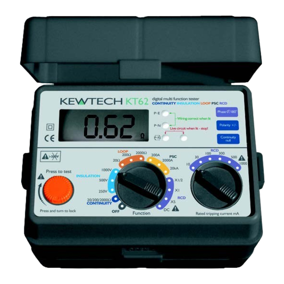
2 Features Connector Live circuit LED Wiring check LED Phase switch Polarity switch LCD display Continuity null switch RCD rated tripping Test button current switch Function switch LCD display Test Lead with IEC Connector Fig. 1 Test Lead for Continuity and Insulation Testing... - Page 6 Features The KT62 Multi-Function tester performs six functions in one instrument. Continuity tester Insulation resistance tester Loop impedance tester Prospective short circuit current tester RCD tester Mains voltage warning when operating the loop impedance and RCD mode. The tester is designed to Safety Standard IEC 1010-1/BS EN 61010-1 CAT III(300V).
- Page 7 Loop impedance, PSC and RCD testing functions have the following Features features: Voltage level In the LOOP/PSC/RCD modes, supply voltage is displayed when the instrument is connected to the supply until the test button is pressed. Wiring check Three LEDs indicate if the wiring of the circuit under test is correct.
-
Page 8: Specification
Specification Measurement Specification Function Open Circuit Short Circuit Range Accuracy Voltage (DC) Current Greater than ±(1.5%rdg Greater than 20/200/2000Ω Continuity 200mA as per +3dgt) Auto-Ranging BS7671 Function Open Circuit Rated Range Accuracy Voltage (DC) Current 1mA or greater 20/200MΩ ±(1.5%rdg 250V+40% @ 250kΩ... - Page 9 Specification Trip Current Rated Function Trip Current Accuracy Duration Voltage (AC) Trip Current: 230V+10% 10/30/100/300/ 2000ms -10% +0% of -15% 50Hz 500/1000 mA x 1/2 range at 230V Trip Current: 2000ms 230V+10% 10/30/100/300/ 1000mA +10% -0% of T rip -15% 50Hz 500/1000 mA @200ms range at 230V...
- Page 10 Specification Battery type Eight AA ALKALINE batteries. Low battery warning symbol appears in the display and the buzzer beeps if the battery voltage drops below 7.8V. Operating temperature 0 to +40˚C, relative humidity 80% or less, no and humidity. condensation. Storage temperature -10 to +50˚C, relative humidity 75% or less, and humidity no condensation.
-
Page 11: Continuity (Resistance) Tests
This measurement should not include the resistance of any test leads used. The resistance of the test leads needs to be subtracted from any continuity measurement. The KT62 is provided with a continuity null feature which allows automatic compensation for any test lead resistance. - Page 12 Temporary link between L and E Fig 3 The KT62 is provided with a facility to change the polarity of the test current used by the instrument during continuity tests. To use this function proceed as follows:- 1 Perform a continuity test as outlined in the procedures above.
-
Page 13: Insulation Tests
(usually in less than a second) when the effective capacitor becomes charged. This charge must be removed from the system at the end of the test, a function which is automatically performed by the KT62. If an alternating voltage is applied between the conductors, the system... -
Page 14: Conduction Current
Insulation tests Insulation (acting as dielectric) Conductor (acting as capacitor plates) Fig 4 Capacitive effect 5.1.3 Conduction Current Since the insulation resistance is not infinite, a small leakage current flows through the insulation between conductors. Since Ohm's Law applies, the leakage current can be calculated from applied voltage (V) Leakage current (µA) =... -
Page 15: Total Leakage Current
The system is charged to the full test voltage, and will be dangerous if left with this charge. The KT62 provides an automatic path for discharging current as soon as the test button is released to ensure that the circuit under test is safely discharged. -
Page 16: Preparation For Measurement
5.4 Insulation resistance measurement The KT62 has a selectable, triple test voltage of 250V, 500V and 1000V Select the insulation resistance setting by rotating the function dial to the required test voltage - 250V, 500V or 1000V as indicated under the ‘insulation’... - Page 17 Equipment disconnected Insulation tests All fuses in or circuit breakers closed Mains switch open Switches closed Lamps out Reading not less than 0.5 MΩ Main switch open Note: insulation testing must only be undertaken on de-energised circuits Fig 7 3 If the mains warning lamp lights and/or the buzzer sounds do not press the test button but disconnect the instrument from the circuit.
- Page 18 Insulation tests 6 When testing is complete release the test button before disconnecting the test leads from the circuit or from the appliance. This will ensure that the charge built up by the circuit or the appliance during insulation test is dissipated in the discharge circuit. In the discharging process, an LED illuminates and the live circuit warning buzzer will sound.
-
Page 19: Loop Impedance Tests
Disconnect the instrument from the circuit under test before 6 Loop impedance operating the function switch. tests To select the loop testing range select ‘LOOP’. 6.1 Voltage Measurement When the tester is set to the loop test function, mains voltage is displayed as soon as the instrument is connected for test. - Page 20 If the red LED is lit do not proceed. 1 Set the instrument to loop test 20Ω range. 2 If testing sockets, connect the plug lead to the KT62 and push the moulded plug into the socket to be tested (see Fig 9).
-
Page 21: Loop Impedance At 3 Phase Equipment
a low test current is more susceptible to interference. This current Loop impedance carries the advantage of reducing the risk of the RCD tripping but tests carries the disadvantage that it produces weaker signals for the measurement circuits to process. 8 If the instrument measures greater than 20Ω... - Page 22 Loop impedance WARNING tests Never connect the instrument to two phases at the same time. Testing as described in 6.4 and 6.5 above will measure the Phase-Earth loop impedance. If you wish to measure the Phase-Neutral loop impedance then the same procedure should be followed except the earth clip should be connected to the neutral of the system i.e.: the same point as the black neutral probe.
-
Page 23: Prospective Short Circuit Current (Psc) Tests
WARNING 7 Prospective short circuit Never connect this instrument across two phases. Never attempt current (PSC) to measure the phase to phase prospective short circuit current. tests 7.1 What is Prospective Short Circuit Current? The Prospective Short Circuit or Fault Current at any point within an electrical installation is the current that would flow in the circuit if no circuit protection operated and a complete (very low impedance) short circuit occurred. - Page 24 Prospective Note: 200A PSC range short circuit This range uses complex sampling and averaging routines. Therefore if the current (PSC) circuit under test changes in value during the period when the unit is tests plugged in for test, the resulting measurement displayed will be the average of all values.
-
Page 25: Rcd Tests
Disconnect the instrument from the circuit under test before 8 RCD tests operating the function switch. To select the RCD test range select ‘RCD’. 8.1 Purpose of the RCD test The RCD must be tested to ensure that operation takes place quickly enough to ensure that there is unlikely to be serious danger to a person experiencing an electric shock from the system. -
Page 26: Testing Rcd's Used To Provide Supplementary Protection
RCD tests tester and check the wiring for a possible fault. If the lamps are correctly lit, press the test button to apply half the rated tripping current for 2000 ms, when the RCD should not trip. The PN and PE LEDs should remain on indicating the RCD has not tripped. -
Page 27: Testing Time Delayed Rcds
LEDs will still be on. The test current will flow for nominally 50mS on the x5 range. 8.6 Testing DC sensitive RCDs The KT62 has a facility to test RCDs that are sensitive to DC fault currents. Proceed as follows: Set the RCD rated tripping current. -
Page 28: General
RCD testing. If this sliding cover is damaged so that it fails to perform its function, do not use the instrument and return it to Kewtech for attention. When the display shows the low battery indication,... -
Page 29: Servicing
If this tester should fail to operate correctly, return it to Kewtech stating 12 Servicing the exact nature of the fault. Before returning the instrument ensure that: The leads have been checked for continuity and signs of damage. The continuity mode fuse (situated in the battery compartment) has been checked. - Page 30 Distributor Kewtech Corporation Limited 76 St. Catherine’s Grove Lincoln LN5 8NA KEWTECH www.kewtechcorp.com 92-1619 04-03...
Need help?
Do you have a question about the KT62 and is the answer not in the manual?
Questions and answers