Sign In
Upload
Download
Table of Contents
Contents
Add to my manuals
Delete from my manuals
Share
URL of this page:
HTML Link:
Bookmark this page
Add
Manual will be automatically added to "My Manuals"
Print this page
×
Bookmark added
×
Added to my manuals
Manuals
Brands
TECLABEL Manuals
Printer
DT2205
User manual
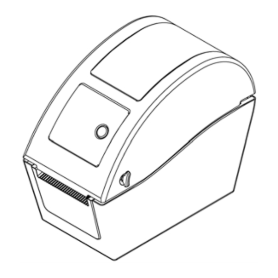
TECLABEL DT2205 User Manual
Direct thermal bar code printer
Hide thumbs
1
Table Of Contents
2
3
4
5
6
7
8
9
10
11
12
13
14
15
16
17
18
19
20
21
22
23
24
25
26
27
28
29
30
31
32
33
34
35
36
37
38
39
40
41
42
page
of
42
Go
/
42
Contents
Table of Contents
Troubleshooting
Bookmarks
Table of Contents
Table of Contents
1 Introduction
Product Introduction
Compliances
2 Operations Overview
Unpacking and Inspection
Printer Overview
Front View
Interior View
Rear View
3 Setup
Setting up the Printer
Loading the Media
Loading External Media (for DT2205 Model Only)
Loading Media in Peel-Off Mode (Option)
Loading Media in Cutter Mode (Option)
Diagnostic Tool
Start the Diagnostic Tool
Printer Function (Calibrate Sensor, Ethernet Setup, RTC Setup
Setting Ethernet by Diagnostic Utility (Option for DT2205 Model)
Using USB Interface to Setup Ethernet Interface
Using Ethernet Interface to Setup Ethernet Interface
Install Microsd Memory Card
Mount the Printer on the Wall
Using the PC USB Keyboard with Printer USB Host Interface (Factory Option for DT039-50 Model)
4 LED and Button Functions
LED Indicator
Regular Button Function
Power on Utilities
Gap/Black Mark Sensor Calibration
Gap/Black Mark Calibration, Self-Test and Dump Mode
Dump Mode
Printer Initialization
Mark Sensor
Set Gap Sensor as Media Sensor and Calibrate the Gap Sensor
Skip AUTO.BAS
5 Troubleshooting
LED Status
Print Problem
LCD Display (Option for DT2205 Model)
6 Maintenance
Revise History
Advertisement
Quick Links
1
Product Introduction
2
Setting up the Printer
3
Diagnostic Tool
4
Printer Function (Calibrate Sensor, Ethernet Setup, Rtc Setup
5
Print Problem
Download this manual
DT2205 / DT039-50
DIRECT THERMAL BAR CODE PRINTER
USER'S
MANUAL
Table of
Contents
Previous
Page
Next
Page
1
2
3
4
5
Advertisement
Table of Contents
Need help?
Do you have a question about the DT2205 and is the answer not in the manual?
Ask a question
Questions and answers
Related Manuals for TECLABEL DT2205
Printer TECLABEL DT039-50 User Manual
Direct thermal bar code printer (42 pages)
This manual is also suitable for:
Dt039-50
Table of Contents
Save PDF
Print
Rename the bookmark
Delete bookmark?
Delete from my manuals?
Login
Sign In
OR
Sign in with Facebook
Sign in with Google
Upload manual
Upload from disk
Upload from URL


Need help?
Do you have a question about the DT2205 and is the answer not in the manual?
Questions and answers