
Summary of Contents for AeroWorks 100cc YAK-54 ARF-QB
- Page 1 100cc YAK-54 ARF-QB (Quick Build) ASSEMBLY MANUAL AEROWORKS 401 Laredo St. Unit “D” - Aurora, CO. 80011 www.aero-works.net...
-
Page 2: Table Of Contents
TABLE OF CONTENTS Page Aeroworks Contact Information ………………………………………………………………. 3 Introduction / Warranty…………………………………………………………………………. 4 Kit Contents……………………………………………………………………………………… 5 Items Needed To Complete ……………………………………………………………………... 7 Tightening and Re-shrinking The Covering ………………………………………………….. 8 Check Seams and Overlaps for Good Seal / Sealing hinge gaps …………………………….. 9 Applying clear covering to the leading edge of wings and stabs………………………………... -
Page 3: Aeroworks Contact Information
Further, Aeroworks reserves the right to change or modify this warranty without notice. In that Aeroworks has no control over the final assembly or materials used for final as- sembly, No liability shall be assumed nor accepted for any damage resulting from the use by the user of the final user-assembled product. -
Page 4: Introduction / Warranty
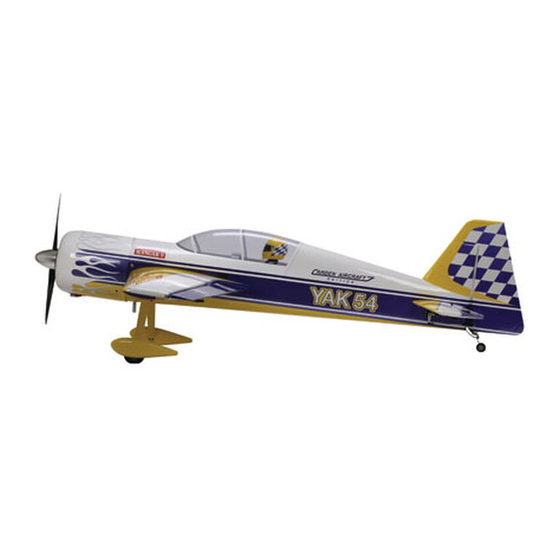
INTRODUCTION Your new 100cc YAK-54 ARF-QB is a highly aerobatic airplane. It is capable of both pre- cision and 3-D maneuvers. The aircraft builds easily, quickly, and precisely due to its state of the art CAD design, LASER cut technology, and high quality included hardware. We hope you enjoy building and flying your 100cc YAK-54 ARF-QB. -
Page 5: Kit Contents
KIT CONTENTS 100cc YAK-54 ARF-QB (1) 3.5(o.d.) x1250mm Antenna guide tube installed (2) 3.5(o.d.) x70mm rudder pull-pull exit tubes Basic Aircraft Parts: installed Fuselage - vertical fin installed – covered, engine box & firewall installed - fuel-proofed - pre drilled for Left Wing with Aileron –... - Page 6 Rudder with (7) pin point hinges (not glued) – covered (2) 4-40 solder coupler Rudder Pre-drilled for the mounting of the control horns (2) 4-40 Metal clevises and tail wheel steering arm. (8) Brass spacers – 4 for ailerons; 2 for elevators; 1 for throttle;...
-
Page 7: Items Needed To Complete
ITEMS NEEDED TO COMPLETE Hardware: • Allen wrenches US and Metric. • Dremel cutting disc and sanding drum tool • Electric drill and selection of bits • Flat head screwdriver • Hobby heat gun • Hobby iron • Masking tape •... -
Page 8: Tightening And Re-Shrinking The Covering
TIGHTENING AND RE-SHRINKING THE COVERING 1. Open your kit slowly and take care not to dam- 3. If bubbles persist, use a small pin to punch holes age any parts of the kit. Remove all parts from in the bubble to relieve trapped air and reheat. their plastic protective covers for inspection. -
Page 9: Check Seams And Overlaps For Good Seal / Sealing Hinge Gaps
It is the responsibility of the purchaser / operator to check the covering seams and overlaps for security and a good seal. Aeroworks is not responsible for failure of covering seams or overlaps during flight. Note: If covering continues to lift apply a small amount of thin CA underneath the covering. -
Page 10: Applying Clear Covering To The Leading Edge Of Wings And Stabs
Applying clear covering to the leading edge of wings and stabs. In order to complete this step you will need: 3. Seal the top and bottom of the leading edge carefully to insure the covering is securely Clear covering, Covering Iron, Scissors, attached to the wood underneath. - Page 11 5. Cut the covering even with the wing tip being 7. Remove the clear backing from the covering. careful not to cut it to short. Note: Do not skip this step. There is a backing to the covering. Take time to remove this backing to get the correct adhesion to the already applied covering.
- Page 12 IMPORTANT It is the users responsibility to check the covering seams and overlaps for security and a good seal. Aeroworks is not re- sponsible for failure of covering seams or overlaps during flight. This is a never ending process that must be done after each flying secession.
-
Page 13: Wing Assembly
WING ASSEMBLY Aileron Servo Installation 1. The ailerons have been pre-hinged and glued to Attach the 18” extension to the outboard servo the wing panels and are ready for flight. No lead and secure with safety wire, string, tape, other steps are necessary for hinging. Clear or other method. - Page 14 Draw the 18” servo extension through the Fasten the pull string from the inboard servo wing and pull through the wing root rib. hole to the male connector of the Y harness. Secure with tape so that the string pulls from to assist in the front end of the connector drawing the servo wire through the wing...
- Page 15 Plug the remaining female end of the Y har- Install servo in servo well with the output arm ness into the male end of the 18” extension toward the leading edge of the wing and mark and secure as before. Secure the servo con- locations of servo mounting holes.
- Page 16 Assemble two pushrod and control horn 13. Repeat mounting steps for other servo so that assemblies as shown. The ball link goes both aileron servos are mounted in bottom of between the left and right sides of the control wing as shown. horn sides and is secured with a nylon lock nut.
- Page 17 4. Use thick CA on each screw prior to 6. Attach 4-40 ball link to the under side of the installing to lock screws in place servo arm using 4-40 bolt, brass spacer and lock nut. Note: CA glues have a fast drying time. Remember to work quickly.
- Page 18 Plug the servos into the receiver and turn on. Carbon reinforcement tube installation Ensure servos are centered and the servo arms are parallel to the aileron hinge line. Adjust Gather the supplied carbon tube for the length of the pushrods so that the aileron is reinforcing the aileron pushrods.
- Page 19 Using a Dremel cut off wheel cut the carbon Remove the 4-40 ball link from the pushrod. tube to correct length. Slide carbon reinforcing tube over the 4-40 pushrod and reassemble ball link to pushrod Remove the 4-40 ball link from the control end.
- Page 20 Final pushrod assembly shown below. Repeat installation steps for all aileron pushrods.
-
Page 21: Stab And Elevator Assembly
STAB AND ELEVATOR ASSEMBLY 3. Assemble two pushrod and control horn assem- Elevator Servo Installation blies as shown. The ball link goes between the 1. The elevators have been pre-hinged and glued to left and right sides of the control horn sides and the stabs and are ready for flight. - Page 22 Install servo in servo well with the output arm Align the control horns over the factory drilled toward the leading edge of the stab and mark holes. locations of servo mounting holes. Use a 1/16 bit to drill servo mounting holes. Use thick CA on each screw prior to Install servo with servo mounting screws.
- Page 23 Align the left and right sides of the control Plug the servo into the receiver and turn on. horns to the mounting holes and mount using Ensure the servo is centered and the servo arm six wood screws as shown. is parallel to the elevator hinge line.
- Page 24 Mark cut location onto carbon tube. Carbon Remove the 4-40 ball link from the control tube should fit between 4-40 ball link lock horn. nuts. Note: Model shown may be different form yours. However, the carbon reinforcement tube installation will remain the same for your model.
- Page 25 Slide carbon reinforcing tube over the 4-40 pushrod and reassemble ball link to pushrod end. Final pushrod assembly shown below. Repeat installation steps for other elevator pushrod.
-
Page 26: Rudder And Tailwheel Assembly
RUDDER AND TAILWHEEL ASSEMBLY Mix epoxy in mixing cup and use a tapered Rudder Installation stick to apply the epoxy inside the pre-drilled holes in the trailing edge of the fin. Apply Gather the rudder, hinges, epoxy, and epoxy to one side of each hinge and insert the materials as shown. - Page 27 5. Epoxy the hinges into the fin first and allow ep- Carefully slide the rudder onto each hinge and oxy to fully cure. against the trailing edge of the fin. Wipe away excess epoxy with alcohol wetted wipes. Note: Ensure you have free and full travel of each hinge.
- Page 28 Rudder Control Horn Installation Align the control horns over the factory drilled holes. Gather the rudder control linkage parts shown below. 2 Rudder cables, 2 4-40 ball link as- semblies, 2 4-40 threaded metal RC links, 4 threaded couplers, 4 brass swaging tubes, 2 left and 2 right side control horns, and 12 wood screws.
- Page 29 Align the left and right sides of the control Attach the Y harness to aft rudder servo leads horns to the mounting holes and mount using and secure with safety wire, string, tape, or six wood screws as shown. other method. Ensure the connectors will not come apart from vibration or light tension.
- Page 30 Mark and use a 1/16 bit to drill the rudder Rudder Pull-Pull Cable Installation servo mounting holes. Gather the rudder control linkage parts shown below. 2 Rudder cables, 2 threaded metal RC links, 4 threaded couplers, and 4 brass swag- ing tubes.
- Page 31 Pull the rudder cables from the fuse tail to the Loop the cable back through the brass swage rudder servo tray. tube as shown. Insert rudder cable through the brass swage Tighten the second loop through the brass tube, then through the threaded coupler hole, swage tube and crimp the brass tube with a and back through the brass swage tube as crimping tool or pliers.
- Page 32 8. Attach a metal threaded RC link to each 10. Use 4-40 rod and 4-40 easy links to connect two threaded coupler. Attach the RC links to the servos together. rudder servo arm and then attach the servo arm to the aft rudder servo as shown. Note: Rudder coupler hardware is not supplied.
- Page 33 Attach the rudder servo coupler assembly to Tape the rudder balance tab to the top leading the rudder servos as shown. Do not tighten the edge of the vertical fin in the neutral position easy link set screws until the rudder servos are as shown.
- Page 34 Slide brass swage onto rudder cable. Loop the cable back through the brass swage tube as shown. Thread the rudder cable through the threaded Pull the loop through the coupler until it is coupler, and back through the brass swage approximately 1/2”...
- Page 35 Hint: If additional crimping is needed a small Adjust rudder pull-pull cables to desired ten- C-Clamp may be used for additional crimping sion by screwing in or out on the threaded cou- pressure. plers and or ball links. Make all adjustments with the rudder servos still powered up and centered, and the rudder still taped in the neu- tral position.
- Page 36 Place tail wheel steering tiller over the pre- Stack the tail wheel leaf springs on the tail drilled holes in the bottom of the rudder. Ap- wheel strut. Position the tail wheel and leaf ply a drop of thick CA to the mounting screws springs on the bottom of the fuse over the pre before inserting into the tiller mounting holes.
- Page 37 Mount the tail wheel strut and leaf springs us- Attach the steering springs on both sides of the ing three wood screws. tail wheel to the rudder tiller and tail wheel tiller. Center the springs between both tillers. Use pliers to twist spring ends closed around the tillers after desired tension and direction adjustments are complete.
-
Page 38: Main Landing Gear Assembly
MAIN LANDING GEAR ASSEMBLY Note that the trailing edge of the landing gear Main Landing Gear Installation strut is tapered. The tapered edge goes toward the rear of the fuse. Gather the landing gear parts as shown below. Landing gear strut, 4 mounting bolts, washers, and lock washers, 2 wheels, 2 axle assemblies, 2 wheel pants and 4 wheel pant mounting bolts with washers. - Page 39 Bolt landing gear strut to fuse with 4 bolts and Wheel And Wheel Pant Installation washers. Ensure tapered edge of the gear strut is facing toward the rear. Gather the 2 wheels, 2 axle assemblies, and 4 wheel collars as shown. Reinstall the landing gear cover.
- Page 40 3. Use two wrenches to screw the lock nut on the Install and tighten the wheel pant mounting wheel axle. bolts to hold the wheel pant in place. DO NOT use Loctite at this time. Note: Do not tighten axle securely yet. Align the flat sides of the axle bolt vertical and Now tighten the axle nut against the landing snug the lock nut against the landing gear...
- Page 41 Remove the wheel pant and use two wrenches Install the wheel and outer wheel collar. Use to permanently tighten the axle to the gear blue Loctite on the wheel collar set screw be- strut. fore final tightening. Install the inner wheel collar on the axle. Use Slide the lock washer then the flat washer on a drop of blue Loctite on the wheel collar set the wheel pant mounting bolts.
- Page 42 Install wheel pants with two mounting bolts. Repeat above steps for other wheel and wheel pant.
-
Page 43: Engine, Muffler Or Canister And Throttle Servo Installation
ENGINE, MUFFLER OR CANISTER AND THROTTLE SERVO INSTALLATION Line up the template with the pre-marked Engine Installation firewall thrust lines. Mark the location of the engine mounting holes. The 100cc YAK-54 will accept a wide range of engine types. Illustrations for a DA-100 installation are provided below. - Page 44 Use a 1/4 drill bit to drill the engine mounting 7. The required distance from the firewall to the holes. front of the prop mount on the engine is 7 3/4” as shown below. Note: The prop hub will stand out from the front of the cowling approximately 1/2”.
- Page 45 Remove the landing gear cover as shown be- Canister Muffler Installation low. Gather the header and canister parts as shown: 1 - 50mm drop flex header (left) 1 - 50mm drop flex header (right) 2 - MTW-75K canisters (front exit) 2 - Teflon couplers 4 - clamps If using standard mufflers, skip the...
- Page 46 Front tunnel floor baffle installed. Slide baffle under wing tube and under the tank floor as shown below. Dry fit the rear tunnel balsa floor baffle for Top view of the installed front and rear tunnel proper fit. Apply medium CA glue to baffle floor baffles.
- Page 47 Dry fit the lower rear former tunnel baffle for Lower rear former tunnel baffle installed. proper fit. Apply medium CA glue to edges of the baffle. Install the lower rear former tunnel baffle as Canister tunnel sealed with the balsa baffles shown below with CA glue.
- Page 48 13. Gather silicon tube for vibration isolation Using a hobby knife, follow the pre marked mounts. Cut eight 7/8” pieces, and insert into and tab cut lines and remove the floor in the the plywood cutouts in the pre-installed canister landing gear cover as shown.
- Page 49 Floor, front and rear cutouts removed from the Use a hobby knife to remove the covering landing gear hatch cover. from the canister tunnel pre cut air exit holes as shown. Reinstall the landing gear cover. Use a sealing Remove the covering from the two front holes iron to ensure the covering is bonded to the of the landing gear cover as shown.
- Page 50 Covering removed from all of the air exit Install the canisters into the canister mounting holes. bracket and into the silicone vibration isola- tors. Temporarily attach the header pipes to the engine as shown to check for proper align- ment and fit. 22.
- Page 51 2. Throttle servo cutout tracing prior to cutting out 4. Use a rotary cutting tool to cut out the throttle servo mounting hole. servo mounting hole. Note: If using standard style mufflers servo Note: Cover engine with a towel or cloth to protect location will be similar.
- Page 52 Cut the throttle pushrod to the proper length. Solder the threaded coupler to the throttle pushrod wire. 7. Gather the soldering tools as shown below. Install the ball links to the throttle pushrod as shown below. Note: For best results we recommend a high quality Silver Solder like “Sta-Brite”...
- Page 53 Mark and use a 1/16” drill bit for the servo Attach the throttle pushrod with the 4/40 ball mounting screws. links and secure. Power up the receiver and throttle servo and adjust pushrod for proper operation. Ensure the servo or rod does not bind or jam at closed or full open positions.
- Page 54 14. Install the header pipes to the engine using blue Reinstall the landing gear cover as shown. Loctite as shown. Note: Use a gasket to ensure good seal Firmly tighten the header mounting screws to Typical standard style muffler installation the engine.
- Page 55 Typical rear carburetor throttle and choke Rear Carburetor and Alternative servo pushrod installation. location for Throttle and Chock Servo Installation If a rear carburetor engine is used or you pre- fer to have the throttle and choke servos installed inside the fuse. Locate the servo mounting brackets, servos and pushrods as shown below.
-
Page 56: Ignition Module Installation
IGNITION MODULE INSTALLATION Roll the supplied foam rubber to make a Ignition module Installation 4 layer pad as shown. Make the pad slightly larger than the ignition module as shown. Position the ignition module inside the engine box to allow both of the spark plug leads to exit and properly connect to the engine with- out excess tension or chafing. - Page 57 Use a 1/4” drill bit to drill the ignition timing Secure the ignition timing connectors with lead hole in the firewall as shown. safety wire, string, tape, or other method. En- sure the connectors will not come apart from vibration or light tension. Enlarge the holes as necessary to pass the igni- tion timing plug through the firewall.
-
Page 58: Fuel Tank Installation
This will keep the weight of the fuel clunk from pulling the fuel line off the brass Note: The fuel “T” and fuel dot are not supplied, tube. but are available through Aeroworks. (Barbs Not Supplied) - Page 59 2. Place the fuel tank on the tank floor and mark Install the foam rubber and nylon ties for the position of the nylon ties for mounting the mounting the fuel tank. tank. Note: If you are not using canister mufflers and have not sheeted the underside of the tank floors.
- Page 60 Cut off excess nylon tie material after tank is Install the fuel tubing as shown securing with firmly installed. small nylon ties. Connect the fuel line to the engine carburetor intake nipple. You will need an after market fuel “T” and fuel filling dot. Note: We recommend using a fuel filter in the line going to the engine carburetor.
- Page 61 Connect the fuel line from the “T” to the fuel Use a 5/16” drill bit to drill the vent line exit dot stopper as shown. Allow enough slack in hole in the balsa tunnel baffle as shown. Pass the line to pull out and connect to the fueling the vent line through the hole to exit out the pump.
- Page 62 Use a 5/16” drill bit to drill the fuel vent exit Remove the landing gear cover and pass the hole in the landing gear cover. fuel vent tubing through the rubber grommet as shown. Install a rubber grommet in the fuel vent exit Cut off excess fuel vent line as shown.
- Page 63 Fuel vent line installed on bottom of fuse.
-
Page 64: Cowl Installation
COWL INSTALLATION Cowl Preparation for 3. Use a felt tip pen to trace the cowl cut outs onto Canister mufflers the bottom of the cowl as shown. 1. Gather the cowl and provided air exit hole Note: Take care and test painted areas prior to templates as shown. - Page 65 5. Cowl cooling air exit holes cut out and edges Cowl cooling air exit holes and canister tunnel sanded smooth. air exit holes in bottom of the fuse. Note: This is only if you are using Canister style mufflers. If you are using Standard style mufflers you will need to cut exhaust stack holes and may need more air flow exiting the bottom of the cowling for proper cooling.
- Page 66 Using a square transfer center line from box Cowl preparation for floor to front of fuse former. Standard style mufflers Gather the materials as shown below. File folder, hobby knife, ruler, tape, marker and pencil. Mark center line of engine box floor. Mark center line on file folder.
- Page 67 Template should fit over cowl ring support of Place masking tape on back side of file folder. front former. Aligning center marks tape template to Lift the template so that it contacts the bottom bottom of fuselage. of the muffler exhaust stacks.
- Page 68 Cut out the exhaust stack holes in template. 9. Trace the location of the exhaust stack exit holes. Note: Removing the tape from the sides of the template will allow the template to lay flat, This will make marking the exhaust stack locations easier.
- Page 69 Trace the sides of the air scoop on bottom of Center mark cowling. cowl. Tape template to cowl. Align the center mark Cut slots in template on both sides of the air of template with the center mark on cowl. Fit scoop of cowl.
- Page 70 Use a rotary cutting tool and sanding drum to Template taped to bottom of cowl with air cut the exhaust stack exit holes as needed. scoop relief cut out. This will allow template to fit flush with cowl. 18. Mark cut locations for exhaust stack exit holes. If necessary using a Dremel drum sander, cut cowl ring to clear engine ignition pickup.
- Page 71 Use a felt tip pen to trace the cowl cut outs on Gather the cowl and provided air exit hole to the bottom of the cowl as shown. templates as shown. Note: Remember not to cut away the front air exit holes.
- Page 72 Use a rotary cutting tool, files, and sandpaper Typical spinner and prop installation to cut out and smooth the edges of the cooling openings in the bottom of the cowl as shown. Typical cut out for standard style mufflers. Note: We have found this to be adequate cooling for the DA100.
-
Page 73: Radio Installation
RADIO INSTALLATION Gather the switches and mounting hardware to 3. Mark location for switches using the switch be used. We used two switches, one for re- mounting plate for a template. ceiver battery, and one for ignition battery. The installation steps are similar for most Note: Fit the wing to the fuselage and check switches. - Page 74 Slide switch wires inside fuse through the 7. Mark location for ignition battery nylon tie switch cutout. mounting hole on side of the engine box Note: The mounting location of the ignition battery is left to the builder. We mount the battery to the engine box side for ease of installation and it can be used for additional nose weight if needed.
- Page 75 Mount the engine ignition battery using nylon Mount the ignition module and regulator if ties and the foam rubber as shown used using nylon ties and mounting screws as shown below. Secure the battery connectors with safety wire, string, tape, or other method. Ensure the con- nectors will not come apart from vibration or light tension.
- Page 76 Gather the radio mounting tray and epoxy Install the radio mounting tray as shown. materials as shown. Note: The radio floor was left out of the model for customers wanting to install canister or full length pipe mufflers. This also allows all customers access to this area if needed.
- Page 77 Mount the receiver battery and regulator as Tape the receiver antenna wire to the radio desired using the radio tray cutouts, nylon ties, mounting tray and to the end of the antenna Velcro and screws. guide tube as shown. This will prevent the antenna wire from vibrating back out.
-
Page 78: Preflight Preparation
PRE-FLIGHT PREPARATION 1. Gather the 4 8-32 wing mounting bolts, 4 #8 Gather the 4 4-40 stab mounting bolts and large rubber backed washers and 4 hair pins. 4 #6 small rubber backed washers. Note: Always check wing attachment bolts are securely tightened. - Page 79 5. Gather the 6 4-40 cowl mounting bolts and 6 #6 7. Gather the 4 4-40 hatch mounting bolts and 4 #6 small rubber backed washers. small rubber backed washers. Note: It is highly recommended you apply thin CA glue to the front hold down dowels. This is a High vibration area and can loosen the front dowels.
-
Page 80: Decal Installation
DECAL INSTALLATION 3. Factory placement of decals. 1. Decals supplied with the kit may vary from the photos below. Decal application steps will be similar. Gather supplied decals, transfer tape, ruler, scis- sors, hobby knife, plastic squeegee or credit card, Windex or Application fluid like Rapid Tac. - Page 81 4. Factory placement of decals shown. Remove backing from Clear transfer tape. 5. Cut transfer tape to accommodate decal size. Apply clear transfer tape over top of decal. Note: Transfer tape will be reused. DO NOT throw away any transfer tape until decal placement is complete.
- Page 82 8. Press transfer tape to top of decal. Spray model surface with application fluid, Windex or soapy water solution. 9. Peel backing from decal. Spray back side of decal with application fluid, Windex or soapy water solution.
- Page 83 12. Position decal in proper location. Application Pull transfer tape from top of decal. Take fluid will allow decal to be moved slightly. care not to pull away or damage decal. Let decal dry. Using a plastic squeegee or credit card. Spread decal smooth and remove all excess application fluid.
-
Page 84: Center Of Gravity / Control Throws
CENTER OF GRAVITY - CONTROL THROWS Center of Gravity Warning, DO NOT skip this step! 3. Start at recommended CG until you are comfort- able with the flight characteristics of the aircraft. The recommended CG is 3.5” back You may find this a bit nose heavy at first but from the wing leading edge at the that is fine to start with. - Page 85 Elevator throw measured in inches at widest Use the supplied flight control deflection me- point of the elevator. . It is ter to measure the throws in degrees recommended you level the model as shown. Rudder throw measured in inches from the Elevator throw measured in degrees.
- Page 86 Aileron throw measured in degrees at widest Control Throw Deflection Table point of the aileron. Low Rate High Rate Aileron 2” or 18˚ up 3” or 30˚ up 2” or 18˚ down 3” or 30˚ down Rudder 2” left 3” left 2”...
-
Page 87: Preflight Check List
Preflight Check List Range check: Do a range check with and without Center of Gravity: Check CG is set properly. the engine running in accordance with the radio manufacturer instructions. If there is insuffi- Engine: The engine should run smoothly at all cient range or a large reduction with the engine throttle settings with smooth transition from running, do not fly until it is resolved! - Page 88 Spins upright and inverted • Flat Spins upright and inverted • Harriers upright and inverted • Water falls • Torque Rolls • Rolling circles • Rolling harrier The sky and your imagination are you only limits. FLY and ENJOY! AEROWORKS World Class Aircraft...
- Page 89 Yak-54 CUSTOMER NOTES ___________________________________________________________________________ ___________________________________________________________________________ ___________________________________________________________________________ ___________________________________________________________________________ ___________________________________________________________________________ ___________________________________________________________________________ ___________________________________________________________________________ ___________________________________________________________________________ ___________________________________________________________________________ ___________________________________________________________________________ ___________________________________________________________________________ ___________________________________________________________________________ ___________________________________________________________________________ ___________________________________________________________________________ ___________________________________________________________________________ ___________________________________________________________________________ ___________________________________________________________________________ ___________________________________________________________________________ ___________________________________________________________________________ ___________________________________________________________________________ __________________________________________________________________________...
Need help?
Do you have a question about the 100cc YAK-54 ARF-QB and is the answer not in the manual?
Questions and answers