Chapters
Table of Contents

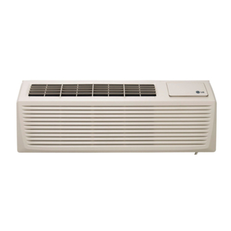
Related Manuals for LG MFL67646801


Summary of Contents for LG MFL67646801
-
Page 1: Air Conditioner
OWNER’S MANUAL AIR CONDITIONER Please read this manual carefully before operating your set and retain it for future reference. TYPE : Room Air Conditioner http://www.lghvac.com www.lg.com P/NO : MFL67646801... -
Page 2: Table Of Contents
Packaged Terminal Air Conditioner/Heat Pump Owner's Manual TABLE OF CONTENTS FOR YOUR RECORDS Safety Precautions......3 Write the model and serial numbers here: Before Operation......7 Model # Serial # Introduction ........8 You can find them on a label on the side of each unit. Dealer's Name Date Purchased Electrical Safety ......9... -
Page 3: Safety Precautions
Safety Precautions Safety Precautions To prevent injury to the user or other people and property damage, the following instructions must be followed. I Incorrect operation due to ignoring instruction will cause harm or damage. The seriousness is classified by the following indications. WARNING This symbol indicates the possibility of death or serious injury. - Page 4 Safety Precautions I Operation Do not place objects on the Use a dedicated circuit for Take the power plug out if power cord. Protect the this appliance. necessary, holding the end cord from being pinched or of the plug and do not touch damaged.
- Page 5 Safety Precautions Do not operate or stop the Do not damage or use an Do not operate with wet unit by inserting or pulling unspecified power cord. hands or in damp out the power plug. environment. • It will cause electric shock or fire •...
- Page 6 Safety Precautions I Operation Do not put a pet or house plant Do not block the inlet or outlet of Use a soft cloth to clean. Do not where it will be exposed to direct air flow. use wax, thinner, or a strong air flow.
-
Page 7: Before Operation
Before Operation Before Operation Preparing for Operation 1. Contact an installation specialist for installation. This is NOT a do-it-yourself project. 2. Plug in the power plug properly. 3. Use a dedicated circuit. 4. Do not use an extension cord. Consult a professional installer or electrician. 5. -
Page 8: Introduction
VERTICAL AIR DEFLECTOR SLEEVE ASSEMBLY (Aluminum Rear Grille) (Horizontal Louver) (Including Aluminum Rear Grille) AIR FILTER INLET GRILLE (Air Intake) EXPANDED METAL GRILLE (For Superior Performance) LG PTAC and PTHP test condition is recommended with expanded metal grille 8 Room Air Conditioner... -
Page 9: Electrical Safety
Electrical Safety Electrical Safety Electrical Data 230V~ 265V~ Power cord may include a current interrupter device. A test and reset button is provided on the plug case. The device should be tested on a periodic basis by first pressing the TEST button and then the RESET button. If the TEST button does not trip or if the RESET button will not stay engaged, discontinue use of the air conditioner and contact a qualified service technician. - Page 10 Electrical Safety Electrical Safety IMPORTANT (PLEASE READ CAREFULLY) Attaching the adapter ground terminal to the wall FOR THE USER'S PERSONAL SAFETY, THIS receptacle cover screw does not ground the APPLIANCE MUST BE PROPERLY GROUNDED appliance unless the cover screw is metal, and not insulated, and the wall receptacle is grounded through the house wiring.
-
Page 11: Installation
") To maintain the best performance NOTICE INSULATION SLEEVE WALL of LG PTAC COOLED HEAT 1. An insulation strip must be attached. The RADIATION insulation strip is provided with the box. INTAKE 2. After assembly of sleeve & Front grille, the 1/4"... -
Page 12: Unit Installation
Installation • UNIT INSTALLATION 1. Remove the shipping screw from the ventilation door. 2. Remove the front gille by pulling it out at the bottom to release it, then lift it up along the unit top front. 3. Slide the unit into the wall sleeve and secure with 6 screws through the unit flange holes. -
Page 13: Control Locations
Control Locations Control Locations Manual Controls • VENTILATION The ventilation lever is located to the lower left side of the unit. The ventilation lever must be in the CLOSE position in order to maintain the best cooling conditions. When fresh air is necessary in the room, set the ventilation lever to the OPEN position. -
Page 14: Fan Speed
Control Locations Electronic Controls The controls will look like one of the following. FAN SPEED • Every time you push this button, it cycles through the settings as follows: {High(F2) ’ Low(F1) ’ High(F2) ’ Low(F1)} E/SAVE HEAT HIGH HIGH POWER COOL COOL... - Page 15 Control Locations Self-Diagnosis FUNCTION: If the unit has a malfunction, a green OPERATION LED located on the Display PCB used by the unit to indicate the errors. USE: If the customer has to register a complaint to the service center, he can be very clear about registering the complaint that what is happening &...
-
Page 16: Additional Controls
Control Locations Additional Controls • REMOVING THE FRONT GRILLE Additional controls are available after removing the front grille and option cover of control box. To remove the front grille, pull out the bottom of front grille and then lift up. To replace the front grille, place the tabs over the top of the unit and push the bottom of front grille until the clips snap... -
Page 17: Energy Saver
Control Locations • REMOTE/LOCAL CONTROL When remote/local switch #1 is on, it allow the unit to operate by the Remote Wall Thermostat. The unit control by knobs are not available. • ENERGY SAVER The energy saver switch #2 is on. This switch is set at cycle fan to provide continuous fan operation in cool or heat modes. - Page 18 Control Locations Disassembly Instructions - Before the following disassembly, POWER SWITCH is set to OFF and disconnected the power cord. 1. Remove the front grille. 2. To remove the front grille, pull out the bottom of the front grille and then lift up. Re-install the component by referring to the removal procedure.
-
Page 19: Maintenance And Service
Maintenance and Service Maintenance and Service TURN THE AIR CONDITIONER OFF AND REMOVE THE PLUG FROM THE POWER OUTLET. Air Filter Cleaning The air filter should be checked at least twice a month to see if cleaning is necessary. Trapped particles in the filter will build up and block the airflow. This reduces the cooling capacity and also causes an accumulation of frost on the cooling coils. - Page 20 Maintenance and Service Drainage The base pan may overflow due to high humidity. To drain the excess water, remove the drain cap from the back of the unit. Drain Cap Chassis The chassis must be cleaned every four months or more often as the atmospheric conditions require.
- Page 21 Maintenance and Service Common Problems and Solutions Troubleshooting Tips save time and money! Review the chart below first and you may not need to call for service. Normal Operation • You may hear a pinging noise caused by water being picked up and thrown by the slinger fan against the condenser on rainy days or when the humidity is high.
- Page 22 Maintenance and Service COMPLAINT CAUSE REMEDY • Check grommets; if worn or missing, replace them. I Grommets • If cracked, out of balance, or partially missing, I Fan replace it. Fan motor noise. • Tighten it. I Loose set screw •...
-
Page 23: Room Air Conditioner Voltage Limits
Maintenance and Service COMPLAINT CAUSE REMEDY • Check the voltage. See the limits on the preceding I Voltage page. If not within limits, call an electrician. • Check overload, if externally mounted. I Overload Replace if open. (If the compressor temperature is high, remove the overload, cool, and retest.) •... - Page 24 Manual del usuario del acondicionador de aire tipo Ventana TABLA DE CONTENIDOS PARA SUS ARCHIVOS Escriba aquí el modelo y número de serie: Precauciones de Seguridad ..2 Modelo n°: Serie n°: Antes de poner el equipo en Puede encontrar estos datos en la etiqueta situada en el lateral de cada unidad.
-
Page 25: Precauciones De Seguridad
Precauciones de Seguridad Precauciones de Seguridad Para evitar lesiones al usuario o a otras personas y daños a la propiedad, estas instrucciones estén seguirse. I Una operación incorrecta por ignorar las instrucciones provocará lesiones o daños. La seriedad se clasifica por las siguientes indicaciones. - Page 26 Precauciones de Seguridad I Operación No use el cable de alimentación No comparta el Saque el enchufe en caso de cerca gas inflamable o materiales tomacorriente con otros necesidad, sosteniendo la combustibles tales como la electrodomésticos. cabeza del enchufe y no lo gasolina, benceno, disolvente, etc.
- Page 27 Precauciones de Seguridad No opere ni detenga la No dañe ni use un enchufe No toque el producto con unidad insertando o de alimentación no las manos mojadas o en un estirando de enchufe. especificado. ambiente húmedo. • De lo contrario, puede provocar •...
- Page 28 Precauciones de Seguridad I Operación No ponga plantas ni animales en No bloquee la entrada ni la salida Utilice un paño suave para la trayectoria que recorrerá el aire del flujo de aire. limpiar. No utilice cera, caliente. disolventes o detergentes fuertes. •...
-
Page 29: Antes De Poner El Equipo En Funcionamiento
Antes de poner el equipo en funcionamiento Antes de poner el equipo en funcionamiento Preparación para el funcionamiento 1. Póngase en contacto con un especialista para realizar la instalación. 2. Enchufe correctamente la toma de alimentación. 3. Utilice un circuito dedicado. 4. -
Page 30: Introducción
(Rejilla de ventilación horizontal) FILTRO DE AIRE REJILLA DE ENTRADA (Entrada de aire) REJILLA METÁLICA EXPANDIDA (Para un rendimiento superior) Se recomienda evaluar el estado de las unidades PTAC y PTHP de LG al utilizar la rejilla metálica expandida. Aparato de aire acondicionado... -
Page 31: Seguraida Electrica
Seguraida Electrica Seguraida Electrica Datos Electricos 230V~ 265V~ El cable de alimentación puede incluir un dispositivo interruptor de corriente. La carcasa del enchufe cuenta con un botón de prueba y otro de reinicio. El dispositivo debe comprobarse periódicamente presionando primero el botón TEST y después RESET. - Page 32 Seguraida Electrica Seguraida Electrica IMPORTANTE PRECAUCION (FAVORLEA CON ATENCIÓN) Adaptar la terminal del ground del adaptador a POR LA SEGURIDAD PERSONAL DEL USUARIO, la cubierta de la pared con un ESTE APARATO DEBE SER DEBÍDAMENTE tornillo no neutraliza el aparato a menos que la NEUTRALIZADO.
-
Page 33: Instalacion
AVISO Para mantener el mejor rendimiento AIRE RADIACIÓN REFRIGERADO del LG PTAC Deberá colocarse una tira de DE CALOR aislamiento. Esta tira viene incluida en la caja. ENTRADA DE AIRE Después del montaje de la caja y la rejilla frontal, Burbuja del nivel de 1/4"... - Page 34 Instalación • INSTALACIÓN DE LA UNIDAD 1. Quite el tornillo de embalaje de la puerta de ventilación. 2. Para ello, quite la rejilla delantera tirando de ella hacia fuera desde la parte inferior y, a continuación, levántela por encima de la parte delantera de la unidad.
-
Page 35: Ubicación De Los Controles
Ubicación de los controles Ubicación de los controles Controles manuales • VENTILACIÓN La palanca de ventilación está ubicada en el lateral izquierdo inferior de la unidad. La palanca de ventilación debe estar en la posición CLOSE para mantener las condiciones de refrigeración óptimas. - Page 36 Ubicación de los controles Controles electrónicos Los controles tendrán el siguiente aspecto: FAN SPEED • Cada vez que pulse este botón, se desplazará por los ajustes de la siguiente forma: {High(F2) Low(F1) High(F2) Low(F1)} ’ ’ ’ E/SAVE HEAT POWER HIGH HIGH •...
- Page 37 Ubicación de los controles Autodiagnóstico FUNCIÓN: Si la unidad sufriera una avería, el LED OPERATIVO verde situado en la pantalla PCB utilizado por la unidad se iluminará para indicar los errores. USO: Si el cliente ha registrado una queja en el Centro de servicio, deberá ser muy claro a la hora de registrar dicha queja, y explicar con nitidez qué...
- Page 38 Ubicación de los controles Controles adicionales • EXTRACCIÓN DE LA REJILLA DELANTERA Los controles adicionales están disponibles al extraer la rejilla delantera y la tapa opcional de la caja de controles. Para extraer la rejilla delantera, tire de la parte inferior de la misma y después hacia arriba.
- Page 39 Ubicación de los controles • CONTROL REMOTO/LOCAL Si el interruptor remoto/local #1 está encendido, la unidad funcionará mediante el termostato remoto de pared. El control de la unidad mediante palancas no está disponible. • AHORRO DE ENERGÍA El interruptor de ahorro de energía #2 está encendido. Este interruptor está ajustado en ventilador de ciclo para el funcionamiento continuo del ventilador en los modos de refrigeración y calefacción.
- Page 40 Ubicación de los controles Instrucciones de desmontaje - Antes de realizar el desmontaje, ajuste en OFF el interruptor POWER SWITCH y desconecte el cable de alimentación. 1. Extraiga la rejilla delantera. 2. Para extraer la rejilla delantera, tire de la parte inferior de la misma hacia fuera y después hacia arriba.
-
Page 41: Mantenimiento Y Asistencia Técnica
Mantenimiento y asistencia técnica Mantenimiento y asistencia técnica APAGUE EL APARATO DE AIRE ACONDICIONADO Y DESENCHUFE LA TOMA DE LA PARED. Limpieza del filtro de aire El filtro del aire se debe revisar al menos dos veces al mes para comprobar si la limpieza es necesaria. - Page 42 Mantenimiento y asistencia técnica Desagüe La bandeja base puede desbordarse debido a un alto nivel de humedad. Retire el tapón del conducto de drenaje en la parte posterior de la unidad para drenar el exceso de agua. Desagüe la tapa Armazón Limpie el armazón cada cuatro meses o con mayor frecuencia según las condiciones atmosféricas.
- Page 43 Mantenimiento y asistencia técnica Problemas comunes y soluciones Los consejos para la resolución de problemas permiten ahorrar tiempo y dinero! Revise la siguiente tabla antes de llamar al servicio técnico. Funcionamiento normal • Es posible que escuche un sonido similar al goteo provocado por el agua que el ventilador recoge y lanza contra el condensador en días lluviosos o cuando los niveles de humedad son muy altos.
- Page 44 Mantenimiento y asistencia técnica PROBLEMA CAUSA SOLUCIÓN • Revise las arandelas aislantes; si están gastadas o I Arandelas aislantes faltan, cámbielas. • Si están agrietadas, desequilibradas o faltan algunas, I Ventilador cámbielas. Ruido en el motor I Tornillo suelto • Apriételas. del ventilador.
- Page 45 Mantenimiento y asistencia técnica PROBLEMA CAUSA SOLUCIÓN • Compruebe el voltaje. Consulte los límites en la I Voltaje página de instrucciones. Si no está dentro de los límites, llame a un electricista. • Compruebe si existe sobrecarga, si está montado en I Sobrecarga el exterior.
- Page 46 Climatiseur de Type Armoire/ Manuel de l utilisateur TABLE DES MATIÈRES INFORMATIONS À Normes de sécurité.......47 CONSERVER Avant la mise en marche ....51 Write the model and serial numbers here: Modèle # : Introduction ........52 Série # : Vous les trouverez sur une étiquette se trouvant sur le côté de Sécurité...
-
Page 47: Normes De Sécurité
Normes de sécurité Normes de sécurité Pour éviter que quelqu un se blesse ou que l appareil subisse des dommages matériels, respectez les indications ci-dessous. I Une utilisation incorrecte par suite de non-respect de ces instructions pourrait causer des dégâts ou endommager l appareil. - Page 48 Normes de sécurité I Utilisation Ne placez aucun objet sur le câble Utilisez un circuit de branchement S il est nécessaire de débrancher, d alimentation. Evitez qu il se perce approprié. faites-le en tenant la prise par ou s endommage. l extrêmité...
- Page 49 Normes de sécurité Ne pas mettre l appareil en marche ou Ne pas abîmer le câble d alimentation Ne pas toucher l appareil avec les l éteindre en le branchant ou en le et n utiliser que celui qui est adapté. mains mouillées ou dans une débranchant.
- Page 50 Normes de sécurité I Utilisation Ne placer ni animal domestique ni Ne bloquer ni l entrée ni la sortie Pour le nettoyage utilisez un chiffon plantes d intérieurs près de la sortie d air doux. N utiliser ni cire, ni diluant ni de l air détergent puissant.
-
Page 51: Avant La Mise En Marche
Avant la mise en marche Avant la mise en marche Préparation 1. Contactez un spécialiste. Il ne s agit pas d un produit « faites-le-vous-même ». 2. Brancher à une prise appropriée. 3. Utilisez un circuit adequat. 4. Ne pas utiliser de rallonge. Consulter un spécialiste en installation ou un électricien. 5. -
Page 52: Introduction
(Inclut la grille d’aluminium) FILTRE À AIR GRILLE D’ENTRÉE (Entrée de l’air) Grille de métal dilaté (Améliore le rendement) Les conditions d'essai LG PTAC et PTHP sont recommandées en cas d'utilisation de la grille en métal déployé Room Air Conditioner... -
Page 53: Sécurité Électrique
Sécurité Électrique Sécurité Électrique Informations électriques 230V~ 265V~ Le cordon d'alimentation peut être équipé d'un interrupteur. Le boîtier du connecteur est équipé d'un bouton de test et d'un bouton de réinitialisation. L'appareil doit être testé régulièrement. Pour cela, appuyez d'abord sur le bouton TEST, puis sur le bouton RESET. Si le bouton TEST ne se déclenche pas ou si le bouton RESET ne reste pas enclenché, arrêtez d'utiliser le climatiseur et contactez un technicien qualifié. - Page 54 Sécurité Électrique Sécurité électrique IMPORTANT (VEUILLEZ LIRE CES INFORMATIONS Le fait de relier la broche de terre de l'adaptateur à la ATTENTIVEMENT) vis du boitier/couvercle de la prise murale ne POUR LA SÉCURITÉ DES UTILISATEURS, CET constitue pas une mise à la terre, à moins que la vis APPAREIL DOIT ÊTRE CORRECTEMENT RELIÉ...
-
Page 55: Installation
S'il y en a un, bouchez-le avec du 318 mm mastic. ") NOTE Pour garantir les performances optimales de LG PTAC. Une bande d'isolation doit ISOLATION MANCHON être fixée. Cette bande d'isolation avec fournie avec AIR REFROIDI RAYONNEMENT DE CHALEUR le pack. - Page 56 Installation • INSTALLATION DEL APPAREIL 1. Enlevez les vis servant au transport de la porte de ventilation. 2. Enlevez la grille frontale en tirant sur la partie inférieure pour la librérer puis relâcher, soulevez-la ensuite le long de l appareil jusqu à la partie supérieure.
-
Page 57: Emplacement Des Contrôles
Emplacement des contrôles Emplacement des contrôles Contrôles Manuels • VENTILATION Le levier de ventilation se trouve sur le bas du côté gauche de l appareil. Ce levier doit être en position CLOSE afin de maintenir les meilleures conditions de refroidissement. Lorsqu il est nécessaire de VENT renouveler l air de la pièce, mettre le levier en position OPEN. - Page 58 Emplacement des contrôles Contrôles Électroniques Les contrôles apparaîtront comme suit. VITESSE DU VENTILATEUR • Chaque fois que vous poussez ce bouton il se produit la séquence suivante : {High(F2) ’ Low(F1) ’ High(F2) ’ Low(F1)} E/SAVE HEAT HIGH HIGH MARCHE COOL COOL TIMER...
- Page 59 Emplacement des contrôles AUTO DIAGNOSTIC FONCTION : En cas de problème de fonctionnement OPERATIONLED apparaît en vert, indiquant les erreurs. UTILISEZ : Pour signaler un problème auprès du centre de maintenance/réparation, examinez d'abord attentivement l'appareil et aidez-vous du manuel d'utilisation pour identifier clairement le problème. De cette manière, le technicien pourra préparer le matériel et les outils appropriés pour corriger ce problème.
- Page 60 Emplacement des contrôles Contrôles Supplémentaires • RETIRANT LA GRILLE FRONTALE En retirant la grille frontale et le couvercle de la boîte de commandes on trouve des contrôles supplémentaires. Pour enlever cette grille tirez sur la partie inférieure de celle-ci et levez-la. Pour la remettre en place, placez les onglets sur le haut de l appareil et poussez le bas de la grille jusqu à...
- Page 61 Emplacement des contrôles • TÉLÉCOMMANDE / COMMANDE SUR L'APPAREIL Lorsque le commutateur n° 1 de la télécommande ou de la commande sur l'appareil est activé (ON), l'appareil peut être commandé par le thermostat mural. Dans ce cas, l'appareil ne peut pas être commandé par les boutons. •...
- Page 62 Emplacement des contrôles Instructions pour le démontage de l appareil Avant d'ouvrir ou de démonter l'appareil, mettez L'INTERRUPTEUR D'ALIMENTATION de l'appareil sur OFF (arrêt) et débranchez le cordon d'alimentation. 1. Retirez la grille frontale 2. Pour retirer celle-ci tirez vers vous la partie inférieure et soulevez-la.
-
Page 63: Entretien Et Service
Entretien et Service Entretien et Service ARRÊTEZ LE CLIMATISEUR ET DÉBRANCHEZ-LE Nettoyage du Filtre à Air Le filtre à air devrait être vérifié au moins deux fois par mois pour voir s il est nécessaire de le nettoyer. Les particules qui s accumulent dans le filtre peuvent bloquer le flux d'air. - Page 64 Entretien et Service Drainage En cas d humidité élevée le réceptacle de la base peut se remplir d eau. Pour vider cet eau en excès, retirez la capsule du drain qui se trouve derrière l appareil. CAPSULE DU DRAIN Châssis Le châssis doit être nettoyé...
- Page 65 Entretien et Service Les problèmes communs et les solutions Ces indications de dépannage vous économiseront du temps et de l argent ! Regardez la liste ci-dessous et si votre problème n y figure pas, appelez le service technique. En utilisation normale •...
- Page 66 Entretien et Service PROBLÈME CAUSE SOLUTION • Vérifiez les oeillets; s ils sont absents ou usés, remplacezles. I Oeillets • S il est fissuré, déséquilibré, ou incomplet,remplacez-le- I Ventilateur Bruits du moteur • Resserez-les. I Vissage lache Du ventilateur. • Si les bruits continuent en état de marche, remplacez le moteur. I Repères usagés Si le moteur bourdonne ou des buits apparaissent pendant le fonctionnement, remplacez le moteur.
- Page 67 Entretien et Service PROBLÈME CAUSE SOLUTION • Vérifiez le voltage et leurs limites. S il n est pas compris dans I Voltage celles-ci appelez un électricien. • Vérifiez la surcharge du compresseur si elle est très élevée. I Surcharge Remplacez-le s il est ouvert (Si la température est très élevée, faites-la baisser, refroidir et refaire le test.).
- Page 68 2. Aux dommages au produit causés par accident, vermine, incendie, inondation ou actes de Dieu. 3. Aux réparations lorsque le produit LG est utilisé à des fins autres que normales, utilisation résidentielle unifamiliale ou contraire aux instructions données dans le guide du propriétaire du produit.
- Page 69 LG Packaged Terminal Air Conditioner Limited Warranty - USA Should your LG Packaged Terminal Air Conditioner prove to be defective in materials or workmanship under normal use during the warranty period listed below, LG Electronics will replace the defective part(s). Replacement part(s) will meet intended fit and function of the original part(s).
Need help?
Do you have a question about the MFL67646801 and is the answer not in the manual?
Questions and answers