Table of Contents
Advertisement
Quick Links
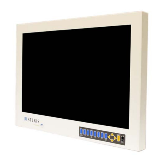
HD3 26" Monitor
LCD Surgical Grade Monitor
High Definition Wide Screen
OPERATION MANUAL
RLM26HD3NPWR
RLM26HD3C
RLM26HD3MCNPWR
RLM26HD3MC
Document #OPM/1300, Revision B
HD3 26" Monitor with fiber input
HD3 26" Monitor with fiber input and power
supply
HD3 26" Monitor with fiber input and integrated
microphone
HD3 26" Monitor with fiber input, integrated microphone,
and power supply
CONFIDENTIAL
© 2013 Copyright VTS Medical Systems, LLC
RLM26HD3C
1 of 29
Advertisement
Table of Contents

Subscribe to Our Youtube Channel
Related Manuals for Steris RLM26HD3NPWR


Summary of Contents for Steris RLM26HD3NPWR
-
Page 1: Operation Manual
HD3 26″ Monitor LCD Surgical Grade Monitor High Definition Wide Screen OPERATION MANUAL RLM26HD3NPWR HD3 26″ Monitor with fiber input RLM26HD3C HD3 26″ Monitor with fiber input and power supply RLM26HD3MCNPWR HD3 26″ Monitor with fiber input and integrated microphone RLM26HD3MC HD3 26″... - Page 2 Notice for Users IMPORTANT: To aid in reporting in the case of loss or theft, or for Part #: service maintenance purposes, please record the monitor’s part number and serial number in the Serial #: space provided. The numbers are located on the back of the monitor.
- Page 3 UL Classified. See complete marking on product. UL Classified part numbers: RLM26HD3C RLM26HD3CNPWR RLM26HD3MC RLM26HD3MCNPWR The UL Classified part numbers RLM26HD3C and RLM26HD3MC include a power supply; model WSX624M, manufactured by Jerome Industries Corporation. The CE marking certifies that this product has met European Union consumer safety, health or environmental requirements.
-
Page 4: Table Of Contents
Table of Contents TIPS AND SAFETY PRECAUTIONS ......................5 CONNECTING THE MONITOR AND TURNING ON/OFF ................6 Step 1: Unpacking the carton ........................6 Step 2: Mounting the monitor ........................6 Step 3: Attaching the monitor to a boom arm and connecting video and power sources ......6 USER INTERFACE ............................ -
Page 5: Tips And Safety Precautions
Tips and Safety Precautions - Image persistence on LCD monitors is caused Location by the continuous display of static graphics on - Use the monitor in a suitable environment. See the screen for extended periods of time. Do not “Operating Temperature” and “Storage display a static image for more than eight (8) Temperature”... -
Page 6: Connecting The Monitor And Turning On/Off
Connecting the Monitor and Turning On/Off Step 1: Unpacking the carton Unpack the monitor and other items from the carton. If any of the items are missing (see checklist on previous page), please call Customer Support at (877) 887-1788. Step 2: Mounting the monitor The back of the monitor (see Figure 1) has a hole pattern that complies to the VESA (Video Electronics Standards Association) mounting standard. - Page 7 VESA Mounting Holes, with Screws Figure 1: Rear view, shown with and without cable cover Figure 2: Close-up of ports Document #OPM/1300, Revision B CONFIDENTIAL © 2013 Copyright VTS Medical Systems, LLC 7 of 29...
-
Page 8: User Interface
User Interface User Interface Buttons The user interface is located on the front, lower right of the monitor. A drawing of the interface is shown below in Figure 3. Figure 3: User Interface Power Control The power is turned on and off by pressing the black P button. - Page 9 Lock Keypad Press to lock the keypad. Unlock Keypad Press simultaneously to unlock the keypad. Keypad Lock can be set to On (active) or OFF (inactive). The On position locks all the buttons on the keypad. When Keypad Lock is active, pressing any of the buttons on the keypad will return a message on the screen that reads “Keypad Locked”.
-
Page 10: Osd (On Screen Display)
OSD (On Screen Display) OSD Navigation OSD Navigation Picture Layout Tune System Backlight Brightness Picture Format Language Analog RGB Calibration Zoom In OSD Setting Contrast Normal YPbPr Calibration 5:4 Stretch* Transparency Phase* Full Screen Reset Calibration Custom OSD Timeout Aspect Frequency* OSD H Position Factory Reset... -
Page 11: Picture Menu
Picture Menu Figure 5: Picture Menu, Brightness – Sharpness Selections Backlight Brightness - The backlight brightness setting increases or decreases the intensity of the backlight. Backlight brightness can be accessed through the OSD menus, as shown above, or using the hot keys “ ” and “... - Page 12 Figure 6: Picture Menu, Color Saturation – Black Stretch Selections Color Saturation - The color saturation setting will change the emphasis of the color component of the image. Tint - The tint setting adjusts the “shade” of the colors. Color Temperature - A pre-configured color temperature can be selected. There are four available: 5500K, 6500K, 7500K and 9300K.
-
Page 13: Layout Menu
Layout Menu Figure 8: Layout Menu, Picture Format – PIP settings Picture Format - The picture format function selects the displayed aspect ratio when the signal input is at a variance with the display panel’s natural/native aspect ratio. Not all settings give different results under certain conditions. - Page 14 – A PIP window is not displayed. – A PIP image from a second channel (see PIP Source Selection below) is displayed in a window within the main image. When PIP is set to ON, the following PIP Adjustments are enabled: PIP Size - There are eight size selections (1-8) available for the PIP window.
- Page 15 Figure 9: Layout Menu, Freeze Frame – Custom Aspect Settings Custom Aspect Settings - A user defined aspect ratio will be saved under “Custom Aspect” in the Picture Format menu when horizontal and vertical offsets are changed in this “Settings” menu. Custom Aspect remains saved when inputs are changed and until the monitor is powered off.
-
Page 16: Tune Menu
Tune Menu Figure 11: Tune Menu Language - English (American) is the only selection. Figure 12: OSD Settings OSD Setting - These settings control the appearance of the OSD. Transparency - The transparency setting enables the OSD to be set to varying levels of transparency. - Page 17 RGB HD Video Color Space - Applicable to RGB signals only. There are two options available for this setting. YUV is used for video timing and RGB is used for VESA/PC timing. RGB is the default. Figure 13: Tune Menu, DVI Video Color Space Setting DVI Video Color Space - Applicable to DVI signals only.
-
Page 18: System Menu
System Menu Figure 14: System Menu Analog RGB Calibration - Applicable to RGB signals only. Calibrates the color response of the RGB input to match the standard color space. This function is for service personnel only. YPbPr Calibration - Applicable to YPbPr signals only. Calibrates the color response of the YPbPr input to match the standard color space. - Page 19 EQ Enable - Applicable to DVI signals only, EQ Enable can be set to On or Off. The default is Off. This option, when ON works as an equalizer to reduce distortion, typically sparkles and vertical lines on the image. Xray Enable - Xray Enable can be set to On or Off.
-
Page 20: Color Calibration Procedure
Color Calibration Procedure Monitors are factory color calibrated. However, RGB, VGA, and YPbPr signal colors may be affected by signal loss over field wiring. If the colors for these signals need adjustment, a field technician can perform the calibration procedure below. Equipment required: •... - Page 21 YPbPr Calibration Connect the video generator to the monitor’s YPbPr input. On the video generator, make the following selections. Proper settings are required for the calibration to be saved. • Signal Type: HDTV/SDTV-YPbPr • Format: 720p60 • Pattern: SMPTEBar pattern, shown below Figure 17: SMPTE Bar Pattern On the monitor, press M to open the OSD menu.
-
Page 22: Default Settings
Default Settings STERIS Part Numbers RLM26HD3C, RLM26HD3CNPWR, RLM26HD3MC, and RLM26HD3MCNPWR Setting Default Setting Default Backlight Brightness Custom Aspect Settings Contrast H Offset Phase Resolution Dependent V Offset Frequency Color Sharpness Red Gain Color Saturation Green Gain Tint Blue Gain Color Temperature... -
Page 23: Monitor Care / Troubleshooting
The user interface buttons do not work products recommended above can be used. - Is keypad lock on? *If the STERIS products are not available, a The image is shifted or not centered mixture of 50% methyl or ethyl alcohol and 50% - In the “Layout”... -
Page 24: Specifications
Specifications RLM26HD3C, RLM26HD3MC, RLM26HD3CNPWR, Part Number RLM26HD3MCNPWR INPUTS: ● Composite / Hi-Line Composite ● S-Video ● RGBS ● ● YPbPr ● ● RGBHV (VGA) ● ● Fiber* ● Display Port ● HD-SDI ● HD-RGBS ● HD-YPbPr ● HD-RGB ● Serial RS232 Control ●... -
Page 25: Glossary
Glossary Backlight Brightness: The intensity of light emitted from the LCD Display. This control is similar to the effect of changing the light behind a stained glass window. As the illumination is increased the overall light output of the image is increased. The proper adjustment takes into consideration the ambient light in the room. - Page 26 Note that Red has been increased by 5% regardless of its original proportion. Since increasing the offset will add additional proportions of the color, care must be taken to assure that variations for very weak and very intense sections of the image do not lose their “Contrast” (ability to detect subtle variations between colors).
-
Page 27: Cable Pin Outs
Cable Pin Outs Description Ring Shield Table 4: Microphone Cable Mini-Jack Connector Pin-Outs Document #OPM/1300, Revision B CONFIDENTIAL © 2013 Copyright VTS Medical Systems, LLC 27 of 29... -
Page 28: Index
Index Analog RGB Calibration, 21 Gamma, 22, 23 Reset Calibration, 21 Glossary, 26 RGB Calibration, 18 Backlight Brightness, 11 Black Stretch, 12, 23 Interface, 8, 24 Safety, 5 Black-Level Offset, 12, 23 Serial Baud Rate, 22, 23 Brightness, 8, 23, 24, 26 Sharpness, 11, 23, 27 Specifications, 2, 5, 24, 25 Keypad Lock, 8, 9... - Page 29 Contact Customer Support 40 Melville Park Road Melville, NY 11747 (877) 887-1788 ® Coverage is a registered trademark of STERIS Corporation Document #OPM/1300, Revision B CONFIDENTIAL © 2013 Copyright VTS Medical Systems, LLC 29 of 29...
Need help?
Do you have a question about the RLM26HD3NPWR and is the answer not in the manual?
Questions and answers