Table of Contents

Subscribe to Our Youtube Channel
Related Manuals for SATA STEAMaster+ SERIES

Summary of Contents for SATA STEAMaster+ SERIES
- Page 1 STEAMaster + SERIES Installation, Operation & Maintenance Manual Frederick, Maryland, U.S.A. STEAMaster+ SERIES Installation, Operation Installation, Operation & Maintenance Manual & Maintenance Manual ELECTRODE STEAM HUMIDIFIERS (10/04)
- Page 2 STEAMaster+ SERIES Installation, Operation & Maintenance Manual IMPORTANT BEFORE INSTALLING OR HANDLING THE HUMIDIFIER PLEASE CAREFULLY READ AND FOLLOW THE INSTRUCTIONS AND SAFETY STANDARDS DESCRIBED IN THIS MANUAL AND ILLUSTRATED ON THE LABELS ATTACHED TO THE MACHINE. This humidifier produces non-pressurized steam by means of electrodes immersed in the water contained in the cylinder-boiler (hereafter called the cylinder).
-
Page 3: Table Of Contents
STEAMaster + SERIES Installation, Operation & Maintenance Manual TABLE OF CONTENTS Models And Description Of The Components ....................... 4 How The STEAMaster+ Works ..........................5 Installation ................................6 Positioning ..............................6 Removing the front cover ..........................7 Fastening to the wall ........................... 7 Plumbing ................................. -
Page 4: Models And Description Of The Components
STEAMaster+ SERIES Installation, Operation & Maintenance Manual Models And Description Of The Components Model Selection =STEAMaster Capacity (KG) H Control Power Version Cylinder Type Plus Internal use only 001 = 3.3 lbs/hr For use with: U = 208/1 1 = Disposable Standard Conductivity 003 = 6.6 lbs/hr... -
Page 5: How The Steamaster+ Works
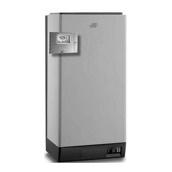
STEAMaster + SERIES Installation, Operation & Maintenance Manual How The STEAMaster+ Works STEAMaster+ is an electrode humidifier. It produces steam for humidification by passing electrode current through the water in the steam generator cylinder between metal electrodes. There are no heater elements. -
Page 6: Installation
STEAMaster+ SERIES Installation, Operation & Maintenance Manual Installation Positioning The STEAMaster+ has been designed for wall mounting (although it can be placed on a stand) and, since it is an atmospheric steam humidifier, should be placed close to the point where the steam will be used, to minimize the steam hose length (and condensate). -
Page 7: Removing The Front Cover
STEAMaster + SERIES Installation, Operation & Maintenance Manual Mounting Removing the front cover The front cover is secured by a capture screw located underneath the SATS logo. Twist the SATS logo to reveal the screw, and use a phillips head screwdriver to remove it. -
Page 8: Plumbing
STEAMaster+ SERIES Installation, Operation & Maintenance Manual Plumbing Water supply The STEAMaster+ must be supplied with water (not softened) having the following characteristics: Model SMP 001-008 009-015 025-045 Instant flow rate 0.2 gpm 0.3 gpm 1 gpm 1.9 gpm Connection 1/4"... - Page 9 STEAMaster + SERIES Installation, Operation & Maintenance Manual Water supply and drain connections are made according to the following diagram. NOTE: Drain line must be trapped under the unit to prevent flash steam from condensing in the unit cabinet. Physical location of the supply and drain connections are located as shown below. SMP 010-015 SMP 025-065 NOTE: SATS can provide a drain tempering system which limits the water drain to no more than 140°F.
-
Page 10: Steam Distribution
STEAMaster+ SERIES Installation, Operation & Maintenance Manual Steam distribution Duct injection If your STEAMaster+ humidifier was supplied with duct steam distributor pipes, they must be mounted completely level in the duct with the steam outlet holes facing up as shown to the right. -
Page 11: Steam Hoses
STEAMaster + SERIES Installation, Operation & Maintenance Manual Steam Hoses NINETY PERCENT (90%) OF ALL OPERATION PROBLEMS ARE CREATED BY IMPROPER STEAM PIPING FROM THE HUMIDIFIER UNIT TO THE DUCT DISTRIBUTOR PIPES. To avoid these problems, remember one simple fact when running the steam hose: steam naturally flows up hill, and condensate naturally flows down hill. -
Page 12: Room Distribution Blower Units
STEAMaster+ SERIES Installation, Operation & Maintenance Manual Room distribution blower units Refer to the manual supplied with the Room Distribution Units for specifics on the blower units themselves. Clearances required are shown below. Minimum dimension (inches) Model SMP001 SMP003 SMP005 SMP008 SMP009 SMP010 SMP015 SMP025 SMP035 SMP045 SMP065... -
Page 13: Power Wiring
STEAMaster + SERIES Installation, Operation & Maintenance Manual Power wiring Single Phase Terminals Three Phase Terminals Check that the power supply voltage to be connected matches the value indicated on the rating plate inside the electrical panel. Insert the power and ground connection cables into the electrical panel compartment using the strain reliefs supplied, and connect to the terminals. - Page 14 STEAMaster+ SERIES Installation, Operation & Maintenance Manual Nominal Turns Wire Voltage Voltage Power Output Output Current Through TA Rate Size Code Phase (kW) (kg/hr) (lbs/hr) (Amps) (mm) Model 208 - 1~N SMP001 1.12 230 - 1~N 208 - 1~N 10.8...
-
Page 15: Control Wiring
STEAMaster + SERIES Installation, Operation & Maintenance Manual Control wiring The STEAMaster+ control system allows up to two sensors to be connected, as well as various safety devices, remote on/off, alarm and serial communications. Generally, the control sensor or humidistat (HT) is located in the room or return air duct. - Page 16 STEAMaster+ SERIES Installation, Operation & Maintenance Manual For Modulating Operation with External Controller: Connect any external controller (0-1 Vdc, 0-10 Vdc Parameter A0 must be set to 1. Parameter A2 must be set per the OUT signal from the regulator: •...
-
Page 17: Aswh / Asdh - Asdh / Asdc Wall - Duct Temperature/Humidity Sensors
STEAMaster + SERIES Installation, Operation & Maintenance Manual ASWH / ASDH – ASDH / ASDC Wall – Duct Temperature/Humidity Sensors Model Description Temperature: NTC thermistor, 10 Kohm at 25°C (77°F) (ASWC/ASDC only) Humidity (0-1 VDC or 4-20 mADC) Accuracy: +- 0.25°C from 0 to 50°C (32 to 122°F) ASWH100000 Wall Humidity sensor (replaces SHWOOP) Humidity: Thin film capacitor ASDH100000 Duct Humidity sensor (replaces SSDOMH00/1) -
Page 18: Hc-101 And Hc-201 Wall And Duct Humidistats
STEAMaster+ SERIES Installation, Operation & Maintenance Manual HC-101 and HC-201 Wall and Duct Humidistats Mounting the HC-101 room humidistat: Mount the HC-101 humidistat to an inside wall or post in the area to be humidified. Position it so that no drafts from registers or outlets are blowing on it. -
Page 19: Pc-301 Air Proving Switch
STEAMaster + SERIES Installation, Operation & Maintenance Manual PC-301 Air Proving Switch Mounting the PC-301 air flow switch: Mount the airflow switch in the supply or return duct using the screws supplied. Mount the device so that the diaphragm is in a vertical position as shown at right. -
Page 20: Start-Up
STEAMaster+ SERIES Installation, Operation & Maintenance Manual Start-Up IMPORTANT WARNINGS: 1. Before starting, check that the humidifier is in perfect condition, that there are no water leaks and that the electrical parts are dry; 2. Do not connect power if the humidifier is damaged or even partially wet! When installation is completed, flush the supply pipe for around 30 minutes by piping water directly into the drain, without sending it into the humidifier;... -
Page 21: The Humicontrol Controller
STEAMaster + SERIES Installation, Operation & Maintenance Manual The HumiControl Controller 1: PRG - Access to most frequently used parameters. Also resets alarm relay. 2: SEL - Displays unit of measure. Press for 2 seconds to access set point. Press with PRG for 5 seconds to enter parameters. -
Page 22: Operation
STEAMaster+ SERIES Installation, Operation & Maintenance Manual Operation Display Information Pressing the SEL button displays the unit of measure currently in use for the main display Holding the button displays the value of the control sensor preceded by the unit of measure. - Page 23 STEAMaster + SERIES Installation, Operation & Maintenance Manual Code Range Default Unit Description Accessible only with hi-limit control P7 (1) St to 100 %RH Hi-limit set point (A0=3) P8 2.0 to 19.9 %RH Hi-limit differential 0 to 100 %RH Hi-limit alarm set point Code Range Default...
- Page 24 STEAMaster+ SERIES Installation, Operation & Maintenance Manual Code Range Default Unit Description Type of outlet sensor; 0=0-1V; 1=0-10V; 2=2-10V; 3=0-20mA; accessible only in 0 to 4 humidity control with 4=4-20mA outlet limiting (A0=3) 0 to A8 %RH Hi-limit sensor minimum...
-
Page 25: Notes About Special Parameters
STEAMaster + SERIES Installation, Operation & Maintenance Manual Parameters for setting the serial connections and remote control: Code Range Unit Description 1= room sensor measurement 2= outlet sensor measurement 3= steam output 1 to 6 Value normally displayed 4= hour counter 5= conductivity 6= current Enable keypad and remote control keypad:... -
Page 26: Standard Factory Settings
STEAMaster+ SERIES Installation, Operation & Maintenance Manual STANDARD FACTORY SETTINGS STEAMaster+ Parameters H Controller STAND ALONE STAND Parameter 0-10 vdc 4-20ma ON / OFF WITH HIGH LIMIT ALONE N/A - Not Accessible ∗ - Read Only (06/06) -
Page 27: Seasonal Shut Down
STEAMaster + SERIES Installation, Operation & Maintenance Manual Seasonal Shut Down During seasonal shut-down or alternatively shut-down for maintenance of the electrical parts and/or the plumb- ing, the humidifier should be placed out-of-service. NOTE: the water cylinder should be emptied before shutting down the humidifier, to prevent corrosion of the electrodes. -
Page 28: Resetting The Hour Counter
STEAMaster+ SERIES Installation, Operation & Maintenance Manual Resetting the Hour Counter To reset the hour counter (parameter d4), proceed as follows: • press the PRG button for 5 seconds, until the code P0 is displayed, indicating the first modifiable parameter;... - Page 29 STEAMaster + SERIES Installation, Operation & Maintenance Manual Controller Action Reset Alarm Reset Humivisor Causes Solution display relay relay 1. Check that the fill pipe from the main to the humidifier and the internal pipe are not blocked or bent and that there is sufficient pressure (0.1-0.8 mpa, 1-8 bar) 2.
- Page 30 STEAMaster+ SERIES Installation, Operation & Maintenance Manual Controller Action Reset Alarm Reset Humivisor Causes Solution display relay relay 1. Reset the default parameters Reprog. Reprog. Internal memory (see Chap. 7.5) Shut- E101 Active error 2. If the problem persists, contact...
- Page 31 STEAMaster + SERIES Installation, Operation & Maintenance Manual Controller Action Reset Alarm Reset Humivisor Causes Solution display relay relay Complete You have activated the manual draining of the drain sequence. Sequence ends on cylinder its own. activated Complete The unit is emptying the cylinder draining for after an extended period of non-use.
-
Page 32: Trouble-Shooting
STEAMaster+ SERIES Installation, Operation & Maintenance Manual Trouble-Shooting problem causes solutions 1. check the safety devices upstream from 1. no electrical power the humidifier and the presence of power 2. on/off switch of the humidifier in 2. close the switch on the panel: position I position 0 (open) 3. -
Page 33: Resetting Factory Defaults
STEAMaster + SERIES Installation, Operation & Maintenance Manual problem causes solutions Water in the cylinder turns black 1. minerals in the cylinder have 1. Check for sags & kinks that overconcentrated and are could trap condensate in the steam deteriorating the electrodes. hoses that could cause a back pressure on the cylinder. -
Page 34: Maintenance
STEAMaster+ SERIES Installation, Operation & Maintenance Manual Maintenance Periodic checks • After one hour of operation: For both disposable and cleanable cylinders, check that there are no significant water leaks. • Every fifteen days or no more than 300 operating hours: For both disposable and openable cylinders check operation, that there are no significant water leaks and the general condition of the cylinder. -
Page 35: Maintenance Of The Other Plumbing Components
STEAMaster + SERIES Installation, Operation & Maintenance Manual Maintenance of the other plumbing components IMPORTANT WARNINGS: • When cleaning the plastic components do not use detergents or solvents; ® ® • Scale can removed using a solution of Lime-A-Way , CLR or 5% phosphoric acid, then rinse with water. -
Page 36: Replacement Parts
STEAMaster+ SERIES Installation, Operation & Maintenance Manual Replacement Parts Single Phase Humidifiers Standard spare parts Model SMP001 SMP003 SMP005 SMP009 Water parts fill cup + conductivity meter 18C453A008 18C453A008 18C453A008 18C453A008 fill valve kit KITVC00006 KITVC00006 KITVC00006 KITVC00012 drain valve kit... -
Page 37: Three Phase Humidifiers
STEAMaster + SERIES Installation, Operation & Maintenance Manual Three Phase Humidifiers Standard Spare Parts Model SMP003 SMP005 SMP008 SMP010 SMP015 SMP025 SMP035 SMP045 SMP065 Water Parts Fill Cup + Conductivity Meter 18C453A008 18C453A008 18C453A008 18C453A008 18C453A008 18C453A008 18C453A008 18C453A008 Fill Valve Kit KITVC00006 KITVC00006 KITVC00006 KITVC00012 KITVC00012 KITVC00040 KITVC00040 KITVC00040... - Page 38 STEAMaster+ SERIES Installation, Operation & Maintenance Manual Spare parts for special applications The following spare parts are supplied separately from the standard humidifier, that is, must be ordered separately. SMP003 SMP005 SMP008 SMP010 SMP015 Disposable Cylinders: 200/*230 Vac 3~, Conductivity 125/350 µS/Cm SMP0T1A00H1 SMP0T2A00H0 SMP0T2A00H0 SMP0T3A00H0 SMP0T3A00H0 400 Vac 3~, Conductivity 125/350 µS/Cm...
-
Page 39: Wiring Diagrams
STEAMaster + SERIES Installation, Operation & Maintenance Manual Wiring Diagrams SMP001, SMP003, SMP005, SMP009 Single Phase (06/06) - Page 40 STEAMaster+ SERIES Installation, Operation & Maintenance Manual SMP003, SMP005, SMP008, SMP010, SMP015 Three Phase (06/06)
- Page 41 STEAMaster + SERIES Installation, Operation & Maintenance Manual SMP025, SMP035, SMP045, SMP065 Three Phase (06/06)
- Page 42 STEAMaster+ SERIES Installation, Operation & Maintenance Manual Wiring of cylinders for SMP025, SMP035, SMP045, SMP065 units and voltages There are 6 electrodes in these cylinders Power Supply - Vac Conductivity Model Micromhos 125 to 350 SMP025 350 to 1250 125 to 350...
-
Page 43: Technical Specifications
STEAMaster + SERIES Installation, Operation & Maintenance Manual Frederick, Maryland USA 21704 Technical Specifications UNIT MODEL NUMBER: CAPACITY, AMPERAGE, WATTAGE Factor Lbs/hr 208 (U) kg/h Amps 10.8 31.4 1.13 2.25 3.75 6.52 Lbs/hr 230 (D) kg/h Amps 16.3 29.3 1.13 2.25 3.75 6.52... - Page 44 STEAMaster+ SERIES Installation, Operation & Maintenance Manual 1572 Tilco Drive Frederick, MD 21704 Corporate Headquarters: Telephone: (301) 620-2033 Facsimile: (301) 620-7820 CyberAiR Sales / Applications: Telephone: (301) 620-2033 Facsimile: (301) 662-5487 Product Support Group (Service, Warranty and Parts) Telephone: (301) 620-2033 Facsimile: (301) 620-1396 E-mail (parts only): parts@stulz-ats.com...
Need help?
Do you have a question about the STEAMaster+ SERIES and is the answer not in the manual?
Questions and answers