Table of Contents
Advertisement
Operating Instructions
GB
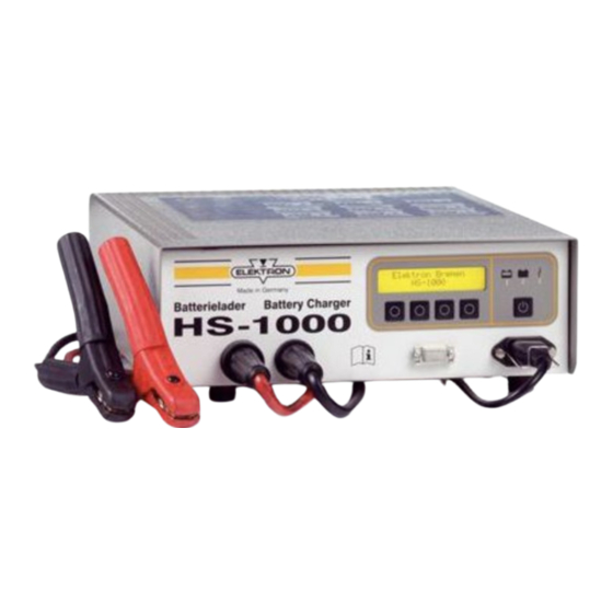
Battery Charger HS-1000
Charger for 12 V and 24 V lead-acid batteries,
charging current up to 70 A
ELEKTRON-BREMEN
Fabrik für Elektrotechnik GmbH
Postfach 10 59 60
D - 28059 Bremen
Fon +49 / (0)421 / 54 90 6-0
Fax +49 / (0)421 / 54 90 619
vertrieb@elektron-bremen.de
www.elektron-bremen.de
Advertisement
Table of Contents
Troubleshooting

Related Manuals for Elektron HS-1000


Summary of Contents for Elektron HS-1000
-
Page 1: Operating Instructions
Operating Instructions Battery Charger HS-1000 Charger for 12 V and 24 V lead-acid batteries, charging current up to 70 A ELEKTRON-BREMEN Fabrik für Elektrotechnik GmbH Postfach 10 59 60 D - 28059 Bremen Fon +49 / (0)421 / 54 90 6-0 Fax +49 / (0)421 / 54 90 619 vertrieb@elektron-bremen.de... - Page 2 "ON/OFF" Button Floating charge, illuminates green when battery is charged "RUN/STOP" Button Charge control, lights up + menu-controlled functions yellow during charging Button "Type of battery" LC-Display + menu-controlled functions "SET" Button (10) Cold appliance plug for mains + menu-controlled functions voltage "MENU"...
-
Page 3: Table Of Contents
Contents Safety notes Discription of the unit Startup Charging / trickle charge / floating mode Backup mode (PSU-Auto) / PSU mode Fault indication and troubleshooting / technical data Operation Operating modes 6.1.1 Auto start feature 6.1.2 Charging 12V / 24V 6.1.3 Selecting battery / setting charging parameters / writing special programs... -
Page 4: Safety Information
Electrical safety: 1.0 Safety information Mains and charging cable must be in perfect condition. If these cables are Connect only lead batteries with damaged in any way, contact the rated voltage of 12 and 24 V! authorized workshop or your expert Caution! Connect only dealer. - Page 5 2.0 Description of the unit Backup mode (PSU Auto mode) The charger replaces the vehicle battery The battery charger HS-1000 can be in case it has to be changed. The on- used to charge 12V and 24V wet board voltage will be maintained.
-
Page 6: Safety Notes
Observe the precautions in the If the battery is discharged by a load, safety notes! the HS-1000 battery charger supplies Observe the handling instructions the required current (within the limits of the battery manufacturer! specified above). -
Page 7: Fault Indication And Troubleshooting
4.0 Fault indication and • This mode remains set until it is deactivated with the "STOP" button. troubleshooting • In the PSU Mode the charger Fault indicator (6) flashes: operates only as a battery reverse- • If temperature of unit is too high voltage, i.e. -
Page 8: Technical Data
The HS-1000 Battery Charger 5.0 Technical data complies with the requirements of the automotive industry and in particular Mains voltage 90 - 260 V fulfils EN 60335, IEC 801 and EN 55011 Mains frequency 50/60 Hz 12 V and 24 V... -
Page 9: Operation
If the charging operation is interrupted by a clip coming off, the charger The HS-1000 battery charger offers a immediately switches back to the standby variety of features and settings. The mode. Charging starts again when a operating structure is clearly arranged, battery is reconnected. -
Page 10: Battery Selection
The momentary battery voltage Ub and charging current Ib are indicated CHARGE 12V MENU SET WET RUN permanently in the upper line. Pressing the "INFO“ button displays the charging time already expired as well as the quantity charged. The display automatically returns to the standard display after 3 s. -
Page 11: Adaptation Of Charging Parameters / Writing Special Programs
6.1.4 Adapting charging parameters / writing special programs 1-4 TIME: 6h00m The four parameters listed above can be adapted to the specific requirements with the "SET" button. First the value for the constant voltage U1 appears: The value can be changed in increments of one minute. -
Page 12: External Power Supply (Psu) 12V + 24V
The default setting "DFT" is given in the CHARGE 12V basic menu. MENU SET TMP RUN Ua = 13.4 V (26.8V) Ia max = 70.0 A (35.0A) This default cannot be changed. However it is possible to switch to the Naturally one of the standard settings adjustment mode by pressing the "SET"... -
Page 13: Support Mode (Psu Auto)
The save operation can be confirmed with the "OK" button or the entire procedure can be aborted with the "ESC" button. Successful storage is confirmed PSU AUTO MENU SET by the display "SAVED“. The display then returns to the basic menu "PSU". Please Note: Changes made become active only when selected in the basic menu. -
Page 14: Service Menu
7.0 Service menu 6-11 START CHARG 12V This menu allows setting to be made, which affect the basic function of the charger. Here it is possible to define limits for the setting ranges, select the language for the displays or set the auto start feature. -
Page 15: Charging Parameters
6-13 F1 0x0000 Save? The last ten fault messages F1 through The changes can be saved by pressing F10 can be viewed by pressing the "+“ the "OK" button again. Press the "ESC“ and "–“ keys. They are output in button to delete the changes;... -
Page 16: Psu Parameters
However observe the following special 6-2 CHARGE MODE feature: 12V 24V The following question appears as the final subpoint: Press the "ESC“ button to return to the 6-276 RELEASE YES basic menu "SERVICE“. Pressing the "12V“ button causes the charger to switch to the 12V parameter limits. - Page 17 When the "PSU" button is pressed the charger switches to the submenu "PSU function" Here it is possible to define 6-312 Ia max 70.0A limits for the adjustment ranges for the external power supply parameters. This makes it possible to allow changes to the charger settings only within extremely close limits to prevent damaging particularly sensitive components in the...
-
Page 18: Fault Indication And Troubleshooting
Explanation: 8.0 Fault indication / If the battery voltage does not reach a trouble shooting minimum voltage of 12V (24V) within 30 minutes, the charging operation is The fault codes (see Chap. 7.1) are aborted with this error. Only a defective given in the titles below. -
Page 19: Reverse Voltage
Explanation: 8.7 Check sum error (0x0008) The charging clips were connected to the wrong poles. Remedy: Connect charging clips to battery terminals with correct polarity: RESTORE DEFAULT VALUES Red clip (+) to positive pole; black clip (-) to negative pole. 8.5 Reverse voltage (0x0800) Explanation: An error is present in the data memory...
Need help?
Do you have a question about the HS-1000 and is the answer not in the manual?
Questions and answers