Table of Contents
Advertisement
Quick Links
Advertisement
Table of Contents

Related Manuals for Tenmars TM-507


Summary of Contents for Tenmars TM-507
- Page 1 INSULATION TESTER TM-507 HB2TM5070000...
-
Page 3: Table Of Contents
CONTENTS SAFETY PRECAUTIONS AND PROCEDURES....................2 1.1. Preliminary instructions ..........................2 1.2. During use ..............................3 1.3. After use ..............................3 1.4. Overvoltage categories - definitions ......................3 GENERAL DESCRIPTION ..........................4 2.1. Working ..............................4 PREPARATION FOR USE ..........................4 3.1. Preliminary checks ...........................4 3.2. Power supply ............................4 3.3. -
Page 4: Safety Precautions And Procedures
TM-507 1. SAFETY PRECAUTIONS AND PROCEDURES This instrument complies with safety Standards EN61557 and EN61010-1 related to electronic measuring instruments. CAUTION For your own safety and to avoid damaging the instrument follow the procedures described in this instruction manual and read carefully all notes... -
Page 5: During Use
TM-507 1.2. DURING USE CAUTION An improper use may damage the instrument and/or its components or injure the operator. Before selecting any function, first disconnect the test leads from the circuit under test. When the instrument is connected to circuits never touch any unused terminal. -
Page 6: General Description
TM-507 2. GENERAL DESCRIPTION Dear Customer, the instrument you have purchased, whether used according to the instructions given in this manual, will grant you accurate and reliable measurements. Thanks to a development of newest conception assuring double insulation and overvoltage category III you will enjoy the highest safety. -
Page 7: Operating Instructions
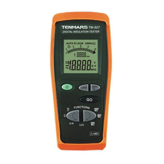
TM-507 4. OPERATING INSTRUCTIONS 4.1. INSTRUMENT - DESCRIPTION LEGEND: 1. Inputs 2. Inputs 3. Display 4. ON/OFF key 5. LOCK key 6. ZERO and backlight key 7. GO key 8. FUNC HOLD key Fig. 1: Instrument description key to switch on/off the instrument... -
Page 8: Dc Voltage Measurement
TM-507 4.2. DC VOLTAGE MEASUREMENT CAUTION The maximum input voltage is 550+10%V. Don’t try to measure higher voltages to avoid risks of electrical shocks or serious damages to the instrument. Fig. 2: Connection of the instrument’s terminals during test Turn on the instrument Press the arrow keys to select 3. -
Page 9: Ac Voltage Measurement
TM-507 4.3. AC VOLTAGE MEASUREMENT CAUTION The maximum input voltage is 550+10%V. Don’t try to measure higher voltages to avoid risks of electrical shocks or serious damages to the instrument. Fig. 3: Connection of the instrument’s terminals during test Turn on the instrument Press the arrow keys to select 3. -
Page 10: Ω : Resistance Measurement And Continuity Test
TM-507 Ω : 4.4. RESISTANCE MEASUREMENT AND CONTINUITY TEST CAUTION Before taking resistance measurements make sure that the circuit under test is not powered and that eventual condensers are discharged. The measured value is out of accuracy if an input voltage is present. -
Page 11: Zero" Mode
TM-507 4.4.1. "ZERO" mode 1. Any addition or replacement of cables, extensions and croco clips nullify the previous calibration and make necessary a new calibration before performing further measurements. Therefore the instrument must be calibrated in the same conditions at which it will operate during measurements 2. -
Page 12: Anomalous Cases Which May Occur During Ω Measurement
TM-507 4.4.2. Anomalous cases which may occur during Ω measurement 1. The full scale of the instrument is 199.9Ω. If the resistance value is higher than this value, or in case of open or interrupted probes, the instrument displays the screen beside. -
Page 13: Loω: Continuity Test On Earth, Protective And Equalizing Potential Conductors
TM-507 4.5. LoΩ: CONTINUITY TEST ON EARTH, PROTECTIVE AND EQUALIZING POTENTIAL CONDUCTORS The measurement is performed with a test current higher than 200 mA (R<5Ω) and open circuit voltage ranging from 4 to 24V DC according to EN 61557-2 and VDE 0413 part 4. -
Page 14: Zero" Mode
TM-507 4.5.1. "ZERO" mode 1. Any addition or replacement of cables, extensions and croco clips nullify the previous calibration and make necessary a new calibration before performing further measurements. Therefore the instrument must be calibrated in the same conditions at which it will operate during measurements 2. -
Page 15: Anomalous Cases Which May Occur During Loω Measurement
TM-507 4.5.2. Anomalous cases which may occur during LoΩ measurement 1. The full scale of the instrument is 19.99Ω. If the resistance value is higher than this value, or in case of open or interrupted probes, the instrument displays the screen beside. -
Page 16: Mω:insulation Resistance Measurement Test Voltage 250V, 500V, 1000V Dc
TM-507 4.6. MΩ:INSULATION RESISTANCE MEASUREMENT TEST VOLTAGE 250V, 500V, 1000V DC The measurement is performed according to EN 61557-2 and VDE 0413 part 1. CAUTION • Before performing the insulation test make sure that the circuit under test is not energized and all relative loads are disconnected. -
Page 17: Measurement Time Setting Mode
TM-507 CAUTION The message on the display means that the instrument is discharging eventual capacitors. During this phase never disconnect nor touch test leads. Nominal test voltage 9. At the end of the test the instrument value automatically discharge eventual capacitors and... -
Page 18: Aintenance
TM-507 5. AINTENANCE 5.1. GENERAL This is a precision instrument. Strictly follow the instructions for use and storage reported in this manual to avoid any possible damage or danger during use. Do not use this tester under unfavorable conditions of high temperature or humidity. Do not expose to direct sunlight. -
Page 19: Technical Specifications
TM-507 6. TECHNICAL SPECIFICATIONS This product conforms to the prescriptions of the European directive on low voltage 73/23/EEC (LVD) and to EMC directive 89/336/EEC, amended by 93/68/EEC. 6.1. CHARACTERISTICS Accuracy is indicated as [% of reading + digit number]. It is referred to the following reference conditions: 23°C ±... -
Page 20: Electrical
TM-507 6.1.1. Electrical Conversion: Average value Display refreshing rate: 2 times per second 6.1.2. Safety standards The instrument complies with: EN61010-1, EN61557 Insulation: Class 2, double insulation Pollution level: Max height: 2000m, indoor use Overvoltage category: CAT III 1000V and CAT IV 600V (phase to earth) -
Page 21: Service
TM-507 7. SERVICE 7.1. WARRANTY CONDITIONS This instrument is guaranteed against material or production defects, in accordance with our general sales conditions. During the warranty period the manufacturer reserves the right to decide either to repair or replace the product. - Page 24 TENMARS ELECTRONICS CO., LTD 6F, 586, RUI GUANG ROAD, NEIHU, TAIPEI 114, TAIWAN. E-mail: service@tenmars.com http://www.tenmars.com...
Need help?
Do you have a question about the TM-507 and is the answer not in the manual?
Questions and answers