Buffalo Nfiniti High Power WZR-HP-G300NH User Manual
Nfiniti high power wireless n router & access point
Hide thumbs
Also See for Nfiniti High Power WZR-HP-G300NH:
- User manual (133 pages) ,
- Setup manual (9 pages) ,
- Specifications (2 pages)

Related Manuals for Buffalo Nfiniti High Power WZR-HP-G300NH


Summary of Contents for Buffalo Nfiniti High Power WZR-HP-G300NH
- Page 1 User Manual for Professional Firmware WZR-HP-G300NH / WZR-HP-G300NH2 Nfiniti High Power Wireless N Router & Access Point www.buffalotech.com 35011943 ver.02...
-
Page 2: Table Of Contents
Introduction 1.1. Welcome 1.2. Device Configuration 1.2.1. Factory Settings 1.2.2. Initial Operation Configuration via the Web Interface 2.1. Preparation 2.2. Web Interface Access 2.3. Web Interface Structure 2.3.1. Setup 2.3.1.1. Basic Configuration 2.3.1.2. Dynamic DNS (DynDNS or DDNS) 2.3.1.3. MAC Address Cloning 2.3.1.4. - Page 3 2.3.8.6. SysInfo Use Cases 3.1. Access Point 3.1.1. Access Point with NAT / DHCP 3.1.1. Access Point attached to a network / Internet gateway 3.2. Wireless Client 3.3. Wireless Client Bridge 3.4. FTP Server 3.4.1. Examples 3.4.2. Logging into the FTP server 3.4.3.
-
Page 4: Introduction
1. Introduction 1.1. Welcome This AirStation wireless router comes with two different firmware packages. You may use either the dd-wrt-based Professional firmware or the simple User-friendly firmware. By default, the Professional firmware is preinstalled for US/EU products, and the User-friendly firmware is preinstalled for Asia-Pacific products. -
Page 5: Configuration Via The Web Interface
Configuration via the Web Interface The router contains an integrated web server that provides an easy to use web interface. It allows configuration, administration, and status checking in a simple but effective way. When accessing the web GUI for the first time, change the default username and password. -
Page 6: Web Interface Structure
2.3. Web Interface Structure - 5 -... -
Page 7: Setup
2.3.1. Setup 2.3.1.1. Basic Configuration Setup Assistant The setup assistant provides a step-by-step interface for basic router configuration. This configures most common settings automatically. WAN Setup Here you’ll find the most important settings to configure your internet access and WAN port. DHCP is enabled by default, but you can also use PPPoE, PPTP, L2TP, static IP, or HeartBeat Signal. -
Page 8: Dynamic Dns (Dyndns Or Ddns)
2.3.1.2. Dynamic DNS (DynDNS or DDNS) Dynamic DNS allows the assignment of a DNS record to a dynamically assigned WAN-side IP address. A DynDNS client updates DNS records when your WAN-side IP address changes. The router’s firmware offers presets for the most common DynDNS services plus an option to define individual settings. -
Page 9: Eoip Tunnel
VLAN Tagging Use this option to configure VLAN tagging. Bridging By default, one bridge (br0) is defined and active. In this section you can define additional bridges and change the interface assignment according to your requirements. Bonding Bonding offers the ability to “bond” interfaces together. Bonding can be used to enhance throughput or provide failover capabilities. - Page 10 WDS Station WDS Station is the client in a WDS-AP <-> WDS station bridge. This is a special wireless networking mode that offers better flexibility and security than the classical MAC address based WDS. WDS AP WDS AP is the AP side for WDS AP <-> WDS Station.
-
Page 11: Wireless Security
2.3.2.2. Wireless Security Because wireless data packets can easily be sniffed, wireless connections require a greater level of security to ensure that data cannot be read by unauthorized users. Security Mode Mode Description Disabled No encryption set (not recommended!) WPA Personal WPA encryption with a passphrase (text password) WPA Enterprise (AP... -
Page 12: Aoss/Wps
2.3.2.3. AOSS/WPS AOSS (AirStation One-touch Secure Setup) is Buffalo Technology’s system to automatically connect wireless clients to an access point. Just press the button on the AirStation, then press the button for the wireless client (which might be in its software). AOSS will connect the wireless devices automatically. -
Page 13: Mac Filter
2.3.2.4. MAC Filter The MAC Filter defines a list of client MAC addresses that are allowed to connect wirelessly. MAC addresses that aren’t on the list aren’t allowed to connect. 2.3.3. Services 2.3.3.1. Services The services section allows the configuration of basic service settings. -
Page 14: Pppoe Server
2.3.3.3. PPPoE Server Some applications require a PPPoE server on the router, which can be configured here. The PPPoE server is disabled by default. 2.3.3.4. The router can also be configured as VPN server or VPN client. PPTP When defining the PPTP server’s IP range, avoid overlap with the range of IP addresses handed out by DHCP if DHCP is enabled. -
Page 15: Hotspot
The User/Password data are entered as follows: <username> * <password> * for example testuser * test * Be careful enabling anonymous login. If anonymous login is enabled, everyone accessing your network has permission to read and write data. 2.3.3.7. Hotspot Most hotspot software requires a server to store user settings and login information. -
Page 16: Port Range Forwarding
forwarded to specific internal devices and computers. Each port forwarding entry defines a source port and a target IP address. Before adding or removing a port forwarding entry, save all changed settings. Any changes not saved will be lost when a port forwarding entry is added or deleted. -
Page 17: Keep Alive
Portuguese, Romanian, Russian, Slovenian, Spanish, and Swedish. default setting is English. Before using Telnet or SSH, activate the associated service(s) in this section. 2.3.7.2. Keep Alive Keep-Alive lets you configure monitoring options that automatically reboot the router if a service malfunction causes it to fail to respond. -
Page 18: Wireless
2.3.8.2. If the WAN interface is enabled, this screen displays WAN settings and throughput statistics. 2.3.8.3. Here you can find LAN-related information like active clients and DHCP clients. 2.3.8.4. Wireless The wireless LAN status screen displays the current wireless LAN interface configuration, wireless LAN clients (in AP modes), and access points (in client modes). -
Page 19: Network Setup
Use Cases The following use cases relate to the most commonly used router configurations. The related router configuration is explained step by step. 3.1. Access Point Access Point (AP, sometimes also called “Infrastructure Mode”) is the mode where the router is also the central wireless hub that connects to the LAN and provides access to wireless devices. -
Page 20: Access Point Attached To A Network / Internet Gateway
Enter your country in “Regulatory Domain” In the “Antenna Gain“ field, please enter the gain of the antenna on your router. The firmware will adjust the transmit power accordingly to meet regulatory requirements. Please keep in mind that very long cables can dampen the HF signal thus reducing the usable antenna gain. -
Page 21: Wireless Client
Enter a name for your wireless network into “Wireless Network Name (SSID)”. Click “Save“. Wireless -> Wireless Security Choose and configure your desired security mode. Please note that WEP is insecure and should only be used if no other option is available. -
Page 22: Wireless Client Bridge
Time Settings o Choose your time zone. Click “Save“. Wireless -> Basic Settings Enter your country in “Regulatory Domain” In the “Antenna Gain“ field, please enter the gain of your AirStation’s antenna. The firmware will adjust the transmit power automatically to meet regulatory requirements. - Page 23 Setup -> Basic Setup WAN Setup o Choose “Disabled” for “Connection Type” (this will be set automatically). Network Setup o Enter the desired LAN-side IP address for the router into “Router IP”. o “Disable“ “DHCP Server”. Time Settings o Choose your time zone.
-
Page 24: Ftp Server
side, a pc in the router’s LAN configured to request an address from DHCP should receive an IP address. 3.4. FTP Server The router can be used as an FTP server when a USB disk (such as a hard disk or flash memory device) is connected to the USB port on the rear of the router. - Page 25 ・Make the settings in the ProFTPD section, and click [Apply Settings]. Setting example: ProFTPD Enable Server Port Files Directory /mnt Allow Write Enable User Password List buffalo 12345678 Anonymous Login Disable (Read-only) Separate the username (example: buffalo) and password (example: 12345678) with a space. - 24 -...
-
Page 26: Logging Into The Ftp Server
3.4.2. Logging into the FTP server ・Open a command prompt window. ・Enter “ftp 192.168.11.1” to access the FTP server. ・Enter the user name, and press the Enter key. ・Enter the password, and press the Enter key. ・When the login is successful, “ftp>” appears on the screen. ・To logout, enter the “bye”... - Page 27 delete Deletes a file on delete the remote computer test1.jpg mdelete Deletes multiple mdelete files on the remote test1.jpg computer test2.jpg test3.jpg rename Renames a file on rename the remote computer test1.jpg new1.jpg help Displays the Help help for FTP commands Exits FTP - 26 -...
-
Page 28: Gpl Statement
GPL Statement The firmware that is used in this product includes software that is subject to the GNU Public Licence (GPL)/the GNU Lesser Public Licence (LGPL). To the extent that it is applicable within the context of the GPL and the LGPL, the conditions of the GPL and the LGPL, as well as the relevant source codes, are available from the manufacturer. -
Page 29: Gnu General Public License – Terms And Conditions Or Copying Distribution And Modification
software. If the software is modified by someone else and passed on, we want its recipients to know that what they have is not the original, so that any problems introduced by others will not reflect on the original authors' reputations. Finally, any free program is threatened constantly by software patents. - Page 30 thereof, to be licensed as a whole at no charge to all third parties under the terms of this License. c) If the modified program normally reads commands interactively when run, you must cause it, when started running for such interactive use in the most ordinary way, to print or display an announcement including an appropriate copyright notice and a notice that there is no warranty (or else, saying that you provide a warranty) and that...
- Page 31 The source code for a work means the preferred form of the work for making modifications to it. For an executable work, complete source code means all the source code for all modules it contains, plus any associated interface definition files, plus the scripts used to control compilation and installation of the executable.
-
Page 32: No Warranty
apply and the section as a whole is intended to apply in other circumstances. It is not the purpose of this section to induce you to infringe any patents or other property right claims or to contest validity of any such claims;... - Page 33 PURPOSE. THE ENTIRE RISK AS TO THE QUALITY AND PERFORMANCE OF THE PROGRAM IS WITH YOU. SHOULD THE PROGRAM PROVE DEFECTIVE, YOU ASSUME THE COST OF ALL NECESSARY SERVICING, REPAIR OR CORRECTION. 12. IN NO EVENT UNLESS REQUIRED BY APPLICABLE LAW OR AGREED TO IN WRITING WILL ANY COPYRIGHT HOLDER, OR ANY OTHER PARTY WHO MAY MODIFY AND/OR REDISTRIBUTE THE PROGRAM AS PERMITTED ABOVE, BE LIABLE TO YOU FOR DAMAGES, INCLUDING ANY GENERAL, SPECIAL, INCIDENTAL OR...
- Page 34 User Manual for User-friendly Firmware Nfiniti High Power Wireless Router & Access Point WZR-HP-G300NH / WZR-HP-G300NH2 www.buffalotech.com...
- Page 35 Contents Chapter 1 - Product Overview ......... 6 Features .................. 6 300 Mbps High Speed Mode ........... 8 Package Contents ..............8 Hardware Overview ..............9 Front Panel LEDs ................9 Back Panel ..................11 Bottom .................... 12 Right Side ..................13 Chapter 2 - Placing Your AirStation ........
- Page 36 LAN ....................37 DHCP Lease (Router Mode only) ..........39 NAT (Router Mode only) ..............40 Route ..................... 41 Wireless Config ............... 42 WPS ....................42 AOSS ..................... 43 Basic ....................45 Advanced ..................48 WMM ....................49 MAC Filter ..................51 Multicast Control ................
- Page 37 Password ..................78 Time/Date ..................79 NTP ....................80 ECO ....................81 Network-USB ................. 83 Access ................... 84 Log ....................85 Save/Restore ................. 86 Initialize/Restart ................87 Update ................... 88 Diagnostic ................89 System Info ..................89 Logs ....................91 Packet Info ..................
- Page 38 Chapter 6 - Troubleshooting ..........105 Cannot connect to the Internet over wired connection.... 105 Cannot access the web-based configuration Interface... 105 Cannot connect to the network wirelessly....... 106 You forgot AirStation's SSID, Encryption Key, or Password..106 The link speed is slower than 300 Mbps (Maximum link speed is only 130 Mbps).
- Page 39 Chapter 11 - Restoring the Default Configuration ...132 Chapter 12 - Shared Folders and the USB Port ..... 133 - 5 -...
-
Page 40: Chapter 1 - Product Overview
Note : Most of this manual documents the user-friendly version of the firmware. For more information on the dd-wrt-based professional firmware, consult the help files in its web- based configuration interface or the WZR-HP-G300NH / WZR-HP-G300NH2 User Manual for Professional Firmware, available for download from Buffalo Technology. Features Supports IEEE802.11n and IEEE802.11b/g With support for current Wireless-N, Wireless-G, and Wireless-B standards, the AirStation can transfer data to and from all standard 2.4 GHz wireless clients. - Page 41 Chapter 1 Product Overview Automatic Channel Selection Monitors wireless interference and automatically assigns the clearest, best channel. Roaming You can use multiple AirStations to cover a large area. Wireless clients can automatically switch AirStations for the best signal. Initialization To restore settings back to the factory defaults, hold down the Reset button on the bottom of the unit.
-
Page 42: 300 Mbps High Speed Mode
Chapter 1 Product Overview 300 Mbps High Speed Mode 300 Mbps is the link speed when using Wireless-N mode. It represents actual wireless data speeds, including overhead. Because the overhead is not available for user data transfer, usable wireless throughput will be substantially slower. Package Contents The following items are included in your AirStation package. -
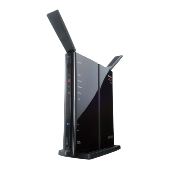
Page 43: Hardware Overview
Chapter 1 Product Overview Hardware Overview Front Panel LEDs AOSS Button To initiate AOSS, hold down this button until the Security LED flashes (about 1 second). Then, push or click the AOSS button on your wireless client device to complete the connection. - Page 44 Chapter 1 Product Overview Diag LED (Red) This indicates the status of this unit depending on the number of blinks per cycle. Note: When the unit is first turned on or restarted, the Diag LED will blink for almost a minute during boot. This is normal. Diag LED Meaning Status...
-
Page 45: Back Panel
Chapter 1 Product Overview Back Panel Router Switch Switches router mode between enabled, disabled, and auto. Router functionality is enabled (router mode). ROUTER Off: Router functionality is disabled (bridge/AP AUTO mode). Auto: This switches between modes automatically EJECT based on whether or not another router is detected on the Internet port. -
Page 46: Bottom
Chapter 1 Product Overview Internet Port 10 Mbps, 100 Mbps, and 1000 Mbps connections are supported. Note: In bridge/AP mode (router switch off ), the Internet port becomes a regular LAN port, for a total of 5 usable LAN ports. Internet LED (Green) The Internet port is connected. -
Page 47: Right Side
Chapter 1 Product Overview Right Side Note: The right side of the unit may become hot. Please be careful not to place anything next to it that could be damaged by heat. Factory Default Settings This sticker shows the AirStation’s SSID, default encryption key, and WPS PIN code. -
Page 48: Chapter 2 - Placing Your Airstation
Chapter 2 - Placing Your AirStation Vertical Placement If the AirStation is to be placed vertically, attach the stand as shown. Horizontal Placement The stand is not used if the AirStation is placed horizontally. - 14 -... -
Page 49: Wall-Mounting
Chapter 2 Placing Your AirStation Wall-Mounting To wall-mount the AirStation, attach FRONT the stand to the wall with the two screws (included). 8.6 cm (~3.4 inches) Snap the center of the AirStation to the stand as shown. FRONT - 15 -... -
Page 50: Chapter 3 - Installation
Chapter 3 - Installation Initial Setup To configure your AirStation, follow the procedure below. Verify that you can connect to the internet without the AirStation, then turn off your modem and computer. Unplug the LAN cable which connects 2) disconnect your computer and modem. - Page 51 Chapter 3 Installation Connect your computer to one of the AirStation’s LAN ports with the LAN cable. AirStation 2) connect 1) connect computer LAN cable Turn on the AirStation, wait one minute, then turn on your computer. AirStation 1) Connect the power supply power outlet Once your computer has booted, the AirStation’s LEDs should be lit as described below: Power...
- Page 52 Chapter 3 Installation Launch a web browser. If the home screen is displayed, setup is complete. If username and password fields are displayed, enter “root” for the username. Enter “admin” for the password if you’re using the professional firmware (default), or leave the password field blank if you’ve switched to the user-friendly firmware.
- Page 53 Chapter 3 Installation Changing Firmware To change between the professional firmware (dd-wrt) and the user-friendly firmware, follow the steps below. Open the configuration Interface of the AirStation. To replace the professional firmware with the user-friendly firmware, click [Administration] > [Firmware Upgrade]. To replace the user-friendly firmware with the professional firmware, go to [Easy Setup] and click [Update AirStation Firmware].
- Page 54 Chapter 3 Installation User-friendly firmware update screen: - 20 -...
-
Page 55: Chapter 4 - Configuration
Chapter 4 - Configuration The web-based configuration tool lets you change advanced settings for the AirStation. Don’t change these settings unless you know what you’re doing. Accessing the Web-based Configuration Interface To configure the AirStation’s advanced settings manually, log in to the web-based configuration interface as shown below. - Page 56 Chapter 4 Configuration This is the configuration interface, where most AirStation settings can be configured. Help is always displayed on the right side of each screen. Refer to the Help screens for more information on using the configuration interface. - 22 -...
-
Page 57: Configuration Interface Menus In Router Mode
Chapter 4 Configuration Configuration Interface Menus in Router Mode The menu structure for the AirStation in router mode is as follows. Please refer to the pages listed at right for explanations of each item. Main screen Descriptions Page Internet/LAN Internet Configure Internet side port and settings. - Page 58 Chapter 4 Configuration UPnP Configure UPnP (Universal Plug and Play). Page 61 Configure priority for packets that require a guaranteed data flow. Page 62 Movie Engine Configure options for the Movie Engine feature. Page 64 Disk Management View the status and configure of attached USB disks. Page 66 Shared Folder Set the USB disk to use as shared folders.
-
Page 59: Configuration Interface Menus In Bridge Mode
Chapter 4 Configuration Configuration Interface Menus in Bridge Mode The menu structure in bridge mode is as follows. Please refer to the pages listed at right for explanations of each item. Main screen Descriptions Page LAN Config Configure LAN side ports and devices. Page 37 Route Configure the AirStation’s IP communication route. - Page 60 Chapter 4 Configuration Configure the AirStation to synchronize with an NTP server to Page 80 automatically set the AirStation’s internal clock. Configure ECO Mode. Page 81 Configure Network-USB from this screen. Page 83 Access Configure access restrictions to the AirStation’s configuration interface. Page 84 Check the AirStation’s logs.
-
Page 61: Setup
Chapter 4 Configuration Setup Setup is the home page of the configuration interface. You can verify settings and the status of the AirStation here. Parameter Meaning Internet/LAN (LAN Config) Displays the configuration screen for the Internet port and LAN ports. Wireless Config Click this button to display the configuration screen for wireless settings. - Page 62 Chapter 4 Configuration Parameter Meaning Click this button to display the configuration screen for NAS settings. Admin Config Click this button to display the configuration screen for administration settings. Diagnostic Click this button to display the status of the AirStation. Easy Setup Enables you to easily configure the AirStation’s network settings automatically.
-
Page 63: Internet/Lan (Lan Config)
Chapter 4 Configuration Internet/LAN (LAN Config) Internet (Router Mode only) Configure the WAN-side port (“Internet port”). Parameter Meaning Method of Acquiring IP Address Specify how the WAN-side IP address is obtained. Default Gateway Configure an IP address for the default gateway. Address of DNS Name Server Specify an IP address for the DNS server. -
Page 64: Pppoe (Router Mode Only)
Chapter 4 Configuration PPPoE (Router Mode only) Configure PPPoE settings. Parameter Meaning Default PPPoE Connection If you have registered multiple connection destinations in the PPPoE Connection List, connection destinations selected here have priority. You need to configure the route to which PPPoE is connected to if you don’t use the default settings. - Page 65 Chapter 4 Configuration Parameter Meaning PPPoE Connection No.*-Add This is displayed when [Edit Connection List] is clicked. Name of Connection Enter the name to identify the connected destination. You may enter up to 32 alphanumerical characters and symbols. Username Enter the username specified by your ISP for PPPoE certification. You may enter up to 32 alphanumerical characters and symbols.
- Page 66 Chapter 4 Configuration Parameter Meaning Keep Alive PPPoE Connection No. *-Add If Keep Alive is enabled, then the AirStation will issue an LCP echo request once a minute in order to maintain the connection with the PPPoE. If the server does not respond for more than 6 minutes, the line is recognized as disconnected and the AirStation will terminate the connection.
-
Page 67: Ddns (Router Mode Only)
Chapter 4 Configuration DDNS (Router Mode only) Configure Dynamic DNS settings. Many settings are only available when the appropriate Dynamic DNS service is enabled. Parameter Meaning Dynamic DNS Service Select a provider (DynDNS or TZO) for Dynamic DNS. Username Enter the Dynamic DNS username. You may enter up to 64 alphanumerical characters and symbols. - Page 68 Chapter 4 Configuration Parameter Meaning IP Address Update Period Specifies the period to notify the dynamic DNS service provider of the current IP address. For DynDNS, set it between 0 and 35 days. For TZO, set it between 0 and 99 days. If 0 (zero) days is set, no periodic update is performed.
-
Page 69: Vpn Server (Router Mode Only)
Chapter 4 Configuration VPN server (Router Mode Only) Configure the VPN server. - 35 -... - Page 70 Chapter 4 Configuration Parameter Meaning Auto Input Click to generate a random IP address. LAN Side IP Address Set a LAN side IP address and subnet mask. DHCP Server Function Enable or disable the DHCP server, which assigns IP addresses automatically.
-
Page 71: Lan
Chapter 4 Configuration Configure LAN-side and DHCP Server settings. Parameter Meaning LAN Side IP Address By default, the LAN side IP address is 192.168.11.1 with subnet mask 255.255.255.0. You may change it here. DHCP Server Function Enable or disable the DHCP server, which assigns LAN-side IP addresses automatically. - Page 72 Chapter 4 Configuration Parameter Meaning DNS Servers Set the DNS server IP address for the DHCP server to issue to * Router Mode only clients. WINS Server Set the WINS server IP address for the DHCP server to issue to * Router Mode only clients.
-
Page 73: Dhcp Lease (Router Mode Only)
Chapter 4 Configuration DHCP Lease (Router Mode only) Configure DHCP Exceptions. Parameter Meaning IP Address Enter an IP address to lease manually. The IP address should be from the same subnet as the DHCP scope, but not be within the range that DHCP is assigning to other devices. -
Page 74: Nat (Router Mode Only)
Chapter 4 Configuration NAT (Router Mode only) Configure network address translation settings. This enables LAN-side devices to communicate with the Internet. Parameter Meaning Address Translation Enable to use Network Address Translation. Log Output of Deleted Packets Enable to log deleted packets (such as errors) during address translation. -
Page 75: Route
Chapter 4 Configuration Route Configure the AirStation’s IP communication route. Parameter Meaning Destination Address Adds a destination IP address and subnet mask to a routing table. Gateway Adds a gateway address to a routing table. Metric The metric is the maximum number of router hops a packet may take on the way to its destination address. -
Page 76: Wireless Config
Chapter 4 Configuration Wireless Config WPS Status and Settings. Parameter Meaning Enable to use WPS automatic configuration. External Registrar Enable to accept configure requests from other WPS devices. Note: Configure requests will not be accepted if AOSS is in use. AirStation PIN Displays the PIN code of the AirStation. -
Page 77: Aoss
Chapter 4 Configuration AOSS AOSS Status and Settings. - 43 -... - Page 78 Chapter 4 Configuration Parameter Meaning Initiates AOSS automatic wireless configuration. Click this, then press or click the AOSS button on your AOSS-compatible wireless client. Repeat for additional AOSS clients. Click this button to disconnect AOSS connections. Note: If AOSS connections are disconnected, the SSID and encryption keys will be restored to their last settings from before AOSS was used.
-
Page 79: Basic
Chapter 4 Configuration Basic The screen to configure a basic wireless settings. Parameter Meaning Wireless Radio Determines whether to allow wireless communication. If this is unchecked, then no wireless connections will be allowed. Wireless Channel Sets a channel (a range of frequencies) for wireless connections. With Auto Channel selected, the AirStation will automatically use the best available channel. - Page 80 Chapter 4 Configuration Parameter Meaning Broadcast SSID If [Allow] is checked, then the AirStation will respond to SSID searches from wireless devices by broadcasting its SSID. If [Allow] is unchecked, then the AirStation ignores SSID searches from wireless devices. Use Multi Security function Clicking [Use Multi Security function] will enable Multi Security, Do not use Multi Security function allowing the use of multiple SSIDs, each with different wireless...
- Page 81 Chapter 4 Configuration Parameter Meaning Wireless encryption You may use any of the following types of encryption: No encryption Data is transmitted without encryption. With this setting, anyone within range can connect to your wireless network and might be able to access data on the network. Not recommended for anyone with private data that needs to be kept secure.
-
Page 82: Advanced
Chapter 4 Configuration Parameter Meaning Rekey interval Set the update interval for the encryption key between 0 and 1440 (minutes). Set up WEP encryption key A WEP encryption key (passphrase) may have any of four different formats. An ASCII passphrase may use either 5 or 13 alphanumeric characters (case-sensitive). -
Page 83: Wmm
Chapter 4 Configuration Set priorities for specific communications. - 49 -... - Page 84 Chapter 4 Configuration Parameter Meaning WMM-EDCA Parameters You don't usually need to change these settings. Using the default settings is recommended. Priority The following priorities may be applied to individual transmission packets: (Highest) 8, (High) 4, (Normal) 2, and (Low) 1. From the queue, these packets are processed in order of priority.
-
Page 85: Mac Filter
Chapter 4 Configuration MAC Filter Restrict access to specific wireless devices. Parameter Meaning Enforce MAC Filtering Enable to restrict wireless connections to devices with registered MAC addresses. Registration List Displays the MAC addresses of registered devices which are permitted to connect wirelessly. Edit Registration List Adds a wireless device to the list of permitted devices. -
Page 86: Multicast Control
Chapter 4 Configuration Multicast Control Configure restrictions on unnecessary multicast packets sent to the wireless LAN port. Parameter Meaning Snooping If enabled, snooping supervises multicast administrative packets such as IGMP and restricts unnecessary multicast transfers to wired or wireless ports. Multicast Aging Time Set the time to hold the data from multicast snooping in the range of 1 to 3600 (seconds). -
Page 87: Wds
Chapter 4 Configuration WDS bridging allows communication between AirStations. Parameter Meaning Check to use WDS bridging. Specify Master/Slave Define this AirStation's role in a WDS bridge. Master This AirStation will be the master in a WDS bridge. It will have the Internet connection, and other AirStations in the bridge will be connected through this AirStation. - Page 88 Chapter 4 Configuration Parameter Meaning SSID Configure the Master Airstation's SSID. [Search] Click to search for other AirStations' SSIDs. Wireless authentication Configure authentication method for the master AirStation Encryption for wireless Choose encryption type for the master AirStation. WPA-PSK (Pre Shared Key) Set the master AirStation's Encryption key.
-
Page 89: Security (Router Mode Only)
Chapter 4 Configuration Security (Router Mode only) Firewall (Router Mode only) Configure the AirStation’s firewall. Parameter Meaning Log Output Enable to output a log of firewall activity. Basic Rules Enable to use any of the quick filters. Preconfigured quick filters include: Prohibit NBT and Microsoft-DS Routing Enabling this blocks communication using these protocols from... - Page 90 Chapter 4 Configuration Parameter Meaning Reject IDENT Requests Enabling this option will answer IDENT requests from the Internet side with corresponding rejection packets. Enable this option if you experienced slow transfer speeds for network applications such as mail, ftp or web browsing. If you have configured transfer of IDENT requests to the LAN side computer in the address translation settings (DMZ or TCP port 113), then that setting has higher priority, and overrides this setting.
-
Page 91: Ip Filter (Router Mode Only)
Chapter 4 Configuration IP Filter (Router Mode only) Edit IP filters. Parameter Meaning Log Output If enabled, IP filter activity is saved to a log. Operation Specify how to process target packets. Direction Specify the transmission direction of target packets. IP Address Specify the sender's IP address and receiver's IP address of the target packets. -
Page 92: Vpn Passthrough (Router Mode Only)
Chapter 4 Configuration VPN Passthrough (Router Mode only) Configure IPv6 passthrough, PPPoE passthrough, and PPTP passthrough. Parameter Meaning IPv6 Passthrough Enable to use IPv6 Passthrough for address translation. PPPoE Passthrough Enable to use PPPoE bridging. PPPoE bridging lets you automatically obtain an IP address from your provider for your LAN- side computer using the PPPoE protocol because PPPoE packets can pass between the Internet and LAN. -
Page 93: Lan Config
Chapter 4 Configuration LAN Config Port Forwarding (Router Mode only) Configure port translation. Parameter Meaning Group Specify a group name for a new rule to belong to. Select [New Group] and enter the new group name in the Group Name field to create a new group. -
Page 94: Dmz (Router Mode Only)
Chapter 4 Configuration Parameter Meaning LAN Side IP Address Enter the LAN side IP address (after translation) for the port translation table entry. LAN Side Port Select the LAN side (after translation) port number (1 - 65535) for the port translation table entry. Port Forwarding Registration Shows current entries in the port translation table. -
Page 95: Upnp (Router Mode Only)
Chapter 4 Configuration UPnP (Router Mode only) Configure UPnP (Universal Plug and Play). Parameter Meaning UPnP Enable or disable Universal Plug and Play (UPnP) functionality. - 61 -... -
Page 96: Qos (Router Mode Only)
Chapter 4 Configuration QoS (Router Mode only) Configure the priority of packets sent to the Internet. Parameter Meaning QoS for transmission to the Internet Determine whether or not to prioritize packets sent to the Internet. Check this box to enable QoS. Upload bandwidth Specify the upstream bandwidth in kbps from the AirStation to the internet side. - Page 97 Chapter 4 Configuration Parameter Meaning priority Select high, medium or low. If packets do not qualify for classification as a type on the list, then their priority is treated as a level between medium and low. - 63 -...
-
Page 98: Movie Engine (Qos)
Chapter 4 Configuration Movie Engine (QoS) Configure Movie Engine options. - 64 -... - Page 99 Chapter 4 Configuration Parameter Meaning Movie Engine switch status Displays the status of the Movie Engine switch. IPv6 Passthrough Set to enable the IPv6 pass-through. Multicast Rate Select the Multicast Control rate. Multicast Control Turn on Multicast Control. TCP Rwin Size Limit Limits the maximum size of TCP Rwin packets passing through the AirStation’s wireless LAN.
-
Page 100: Nas
Chapter 4 Configuration Disk management View the status of and configure attached USB hard disks. Parameter Meaning Device Displays information for attached USB disks. Disks are removed when [Remove] in the Device column is clicked. Disk Assignment A disk number will be automatically assigned to the disk or you can choose a number. - Page 101 Chapter 4 Configuration Parameter Meaning Automatic USB Disk Assignment Check [Use] to automatically select an attached USB hard disk. The entire drive will be used as the shared folder. To configure your disk and share manually, uncheck [Use]. [Use] is selected by default. FAT format file name character code Select the character code for filenames in FAT formatted partitions.
-
Page 102: Shared Folder
Chapter 4 Configuration Shared Folder Configure a USB hard disk for use with shared folders. Parameter Meaning Shared Folder Name* Enter a name for the shared folder. Up to 18 alphanumeric characters, spaces, hyphens (-), and underscores (_) may be used. Shared Folder Description* Enter a description of the shared folder (optional). - Page 103 Chapter 4 Configuration Parameter Meaning Web Access You may also select to enforce access limits on users accessing through Web Access by checking the Access Limits checkbox. Users will have the same access levels as assigned above. If Access Limits is not checked, then all users accessing the shared folder via Web Access will have [Read only] access..
-
Page 104: User Management
Chapter 4 Configuration User Management This screen lets you add users to the access list with the ability to access shared folders. Parameter Meaning Username Enter the name of a user to be given access to the shared folder. Up to 20 alphanumeric characters, space, hyphens (-), and underscores (_) may be used for each user. -
Page 105: Shared Service
Chapter 4 Configuration Shared Service Assign AirStation and workgroup names to access shared folders. Parameter Meaning Shared Folder Enable to make a USB disk available on your local network. AirStation name Rename your AirStation if desired. Up to 15 alphanumeric characters, space, and hyphens (-), may be used. -
Page 106: Web Access
Chapter 4 Configuration Web Access The screen to configure Web Access. Parameter Meaning Web Access Check [Enable] to use Web Access. Web Access Display Language Set the language to be used with Web Access. HTTPS/SSL Encryption Check [Enable] to use SSL encryption for protected data transfer. Web Access External Port Automatically sets the external port used for Web access. - Page 107 Chapter 4 Configuration Parameter Meaning Web Access Displays the status of web access. External Port Status Displays the status of the external port. BuffaloNAS.com Displays the status of BuffaloNAS.com. - 73 -...
-
Page 108: Media Server
Chapter 4 Configuration Media Server Media Server settings. Parameter Meaning Media Server Enable to use the media server. Status Displays the status of the media server. - 74 -... -
Page 109: Bittorrent
Chapter 4 Configuration BitTorrent Configure the BitTorrent client. Parameter Meaning BitTorrent Function Enable to use the BitTorrent client. If the BitTorrent client is enabled, overall communication performance may decrease and settings screens may respond slower. If that happens, reformat the USB disk with XFS. - Page 110 Chapter 4 Configuration Parameter Meaning Bandwidth Restriction Set a bandwidth limit for BitTorrent. [Download Manager] Displays the BitTorrent download manager screen. Add a torrent, then click [Add] to download the file(s). [Delete BitTorrent information] Deletes all files, including the torrent files and files which are currently downloading.
-
Page 111: Admin Config
Chapter 4 Configuration Admin Config Name Configure basic AirStation settings. Parameter Meaning AirStation Name Enter a name for the AirStation. Names may include up to 64 alphanumeric characters and hyphens (-). List Network Services Enable or disable this to display the computers and devices on your network with their supported services. -
Page 112: Password
Chapter 4 Configuration Password Configure the password to log in to the AirStation’s configuration screen. Parameter Meaning Administrator Name The name of the Administrator account is “root”. Administrator Password The Administrator password may contain up to 8 alphanumeric characters and underscores (_). - 78 -... -
Page 113: Time/Date
Chapter 4 Configuration Time/Date Configure the AirStation’s internal clock. Parameter Meaning Local Date You may manually set the date of the AirStation’s internal clock. Local Time You may manually set the time of the AirStation’s internal clock. Time Zone Specify the time zone (offset of Greenwich Mean Time) of the AirStation's internal clock. -
Page 114: Ntp
Chapter 4 Configuration Configure an NTP server to automatically synchronise the AirStation’s internal clock. Parameter Meaning NTP Functionality Enable to use an NTP server. The default is Enabled. NTP Server Enter the name of the NTP server as a hostname, hostname with domain name, or IP address. -
Page 115: Eco
Chapter 4 Configuration Configure Eco mode from this screen. - 81 -... - Page 116 Chapter 4 Configuration Parameter Meaning Schedule feature Enable to schedule Eco Mode. If Eco mode is enabled, AOSS will function only when the AirStation is in Normal operating mode. Weekly schedule Graphically displays the configured schedule. Register schedule Configure operational mode for time periods in the weekly schedule.
-
Page 117: Network-Usb
Chapter 4 Configuration Network-USB Configure Network-USB from this screen. Parameter Meaning Network-USB Network-USB allows sharing USB devices connected to the AirStation from multiple computers on a wired or wireless LAN. Disable to reduce the impact on the NAS and other functions, improve performance, or for security reasons. -
Page 118: Access
Chapter 4 Configuration Access Restrict access to the AirStation’s settings screens. Parameter Meaning Log Output Enabling outputs a log of changes to access settings. Prohibit configuration from wireless If enabled, prevents access to settings screens from wirelessly connected devices (only wired devices may configure). Prohibit configuration from wired If enabled, prevents access to settings screens from wired devices (only wirelessly connected devices may configure). -
Page 119: Log
Chapter 4 Configuration Transfer the AirStation’s logs to a syslog server. Parameter Meaning Log Transfer Enable to send logs to a syslog server. Syslog Server Identify the syslog server by hostname, hostname with domain name, or IP address. You may enter up to 255 alphanumeric characters, hyphens (-), and underscores (_). -
Page 120: Save/Restore
Chapter 4 Configuration Save/Restore Save AirStation settings as a file, and restore from them later. Parameter Meaning Save current settings Clicking [Save] will save the current configuration of the AirStation to a file. If the [Encrypt the configuration file with a password] option is checked, then the configuration file will be password protected with the current administrator password. -
Page 121: Initialize/Restart
Chapter 4 Configuration Initialize/Restart Initialize or restart the AirStation. Parameter Meaning Restart Click [Restart Now] to restart the AirStation. Initialize Click [Initialize Now] to initialize and restart the AirStation. - 87 -... -
Page 122: Update
Chapter 4 Configuration Update Update the AirStation’s firmware. Parameter Meaning Firmware Version Displays the current firmware version of the AirStation. Specify Local File Update Method Updates from a firmware file stored on your computer. Automatic Update (Online Version) Automatically updates to the latest firmware available. Firmware File Name Click [Browse...] to navigate to the firmware file on your computer if [Specify Local File] was selected. -
Page 123: Diagnostic
Chapter 4 Configuration Diagnostic System Info View system information for the AirStation. - 89 -... - Page 124 Chapter 4 Configuration Parameter Meaning Model Displays the product name of the AirStation and the firmware version. AirStation Name Displays the name of the AirStation. Mode Switch Status Displays the status of the AirStation’s mode switch. Operational Mode Displays the AirStation’s current operational mode. Movie Engine Status Displays the current Movie Engine Status.
-
Page 125: Logs
Chapter 4 Configuration Logs The AirStation’s logs are recorded here. Parameter Meaning Display log info Choose the types of logs to display. Logs Displays the log information recorded in the AirStation. - 91 -... -
Page 126: Packet Info
Chapter 4 Configuration Packet Info View packet transfer information. Parameter Meaning Sent Displays the number of packets sent to the WAN, the LAN, and the wireless LAN. Received Displays the number of packets received from the WAN, the LAN, and the wireless LAN. - 92 -... -
Page 127: Client Monitor
Chapter 4 Configuration Client Monitor This screen shows devices that are connected to the AirStation. Parameter Meaning Client Monitor Displays information (MAC address, lease IP address, hostname, communication method, wireless authentication and 802.11n) for devices that are connected to the AirStation. - 93 -... -
Page 128: Ping
Chapter 4 Configuration Ping A ping test checks whether the AirStation can communicate with a specific network device. Parameter Meaning Destination Address Enter the IP address or hostname of the device that you are testing communication with, then click [Execute]. The result will be displayed below. -
Page 129: Chapter 5 - Connect To A Wireless Network
Game console (AOSS Devices) • Before using AOSS/WPS to connect to a Buffalo wireless client, install Client Manager software from the included utility CD. Consult your wireless client’s documentation for more information. • Buffalo’s Client Manager software can be used with the wireless LAN devices built into most computers. -
Page 130: Windows 7/Vista (Client Manager V)
If you are using Windows 7 or Vista, use the included Client Manager V software to connect wirelessly with AOSS/WPS. Click [Start] > [All Programs] > [BUFFALO] > [AirStation Utility] > [Client Manager V]. Click [Create Profi le]. If the User Account Control screen opens, click [Yes] or [Continue]. -
Page 131: Windows Xp (Client Manager 3)
Chapter 5 Connect to a Wireless Network Windows XP (Client Manager 3) If you are using Windows XP, use Client Manager 3 to connect wirelessly with AOSS/WPS. Right click on the icon in the system tray and select [Profi le]. Click the [WPS AOSS] button. -
Page 132: Mac Os X (Aoss Assistant)
Chapter 5 Connect to a Wireless Network Mac OS X (AOSS Assistant) If you are using Mac OS X 10.7 / 10.6 / 10.5 / 10.4, use the included AOSS Assistant software to connect wirelessly with AOSS. Load the utility CD in your Macintosh. From the menu bar, click [Go] >... -
Page 133: Other Devices (E.g. Game Console)
Chapter 5 Connect to a Wireless Network Other Devices (e.g. Game Console) If you are using a game machine which supports AOSS or WPS, refer to that device’s manual to initiate AOSS/WPS. When instructed, hold down the AOSS button on the AirStation for 1 second. When the Security LED on the front of the AirStation stop flashing and glows steadily, the connection is complete. -
Page 134: Windows Vista (Wlan Autoconfig)
Chapter 5 Connect to a Wireless Network Enter the encryption key and click [OK]. Windows Vista (WLAN AutoConfig) With Vista, use WLAN AutoConfig to connect to the AirStation. Right click on the wireless network icon in the system tray. Click [Connect to a network]. When this screen is displayed, select your network and click [Connect]. - Page 135 Chapter 5 Connect to a Wireless Network If the screen below is displayed, click [I want to enter the network key or passphrase instead]. Otherwise,go to step 4. - 101 -...
- Page 136 Chapter 5 Connect to a Wireless Network Enter the encryption key and click [Connect]. Step through the wizard to finish configuration. If the Set Network Location screen is displayed, select [Home], [Work], or [Public location] depending on where you’re using the AirStation. - 102 -...
-
Page 137: Windows Xp (Wireless Zero Configuration)
Chapter 5 Connect to a Wireless Network Windows XP (Wireless Zero Configuration) Windows XP includes Wireless Zero Config, a built-in utility to connect to your AirStation. Note: If Client Manager 3 is installed on your computer, Wireless Zero Config is disabled. Uninstall Client Manager 3 to use Wireless Zero Config, or just use Client Manager 3 to connect to the AirStation. -
Page 138: Mac Os X (Wi-Fi)
Chapter 5 Connect to a Wireless Network Mac OS X (Wi-Fi) Use Wi-Fi on a Mac to connect to the AirStation. Note: In Mac OS X 10.6 and earlier, “Wi-Fi” appears as “AirPort”. Refer to the label on the side of the AirStation. Make a note of the SSID and KEY printed on the label. -
Page 139: Chapter 6 - Troubleshooting
Chapter 6 - Troubleshooting Cannot connect to the Internet over wired connection. • Make sure that your AirStation is plugged in! • Check that the status LEDs of your AirStation are lit as below: Power Green light is on Router Green light is on or off (depending on your environment) Diag Green light is on or flashing... -
Page 140: Cannot Connect To The Network Wirelessly
Chapter 6 Trouble Shooting Cannot connect to the network wirelessly. • Configure your wireless client with the same SSID, encryption type, and encryption key as set on the AirStation. The factory defaults are: SSID - The AirStation’s MAC address (printed on the label) Encryption Type - WPA/WPA2 mixed mode - PSK (Connect with either WPA-PSK TKIP or WPA2-PSK AES). -
Page 141: Other Tips
How do I enable or modify security encryption settings on the wireless router? Answer: Log in to the configuration interface with your browser. Go to [Wireless Config] - [Security]. Buffalo recommends WPA for wireless encryption. The passphrase/key should be at least 8 characters in length. - Page 142 If an Internet connection IS available with a direct connection to the computer, please call our customer support. Issue: Where can I download the latest drivers, firmware, and instructions for my Buffalo wireless products? Answer: The latest drivers and firmware are available online at www.buffalotech.com...
-
Page 143: Chapter 7 - Default Configuration Settings
Chapter 7 - Default Configuration Settings Feature Parameter Default Setting Internet Method of Acquiring IP Address Perform Easy Setup (Internet Connection Wizard) (Router Mode only) Default Gateway none Address of DNS Name Server none Internet MAC Address Use Default MAC Address MTU Size of Internet Port 1500 Bytes PPPoE... - Page 144 Chapter 7 Default Configuration Settings Feature Parameter Default Setting LAN Side IP Address Router Mode (Router Switch AUTO/ON): 192.168.11.1 (255.255.255.0) Bridge Mode (Router Switch OFF): 192.168.11.100 (255.255.255.0) Bridge Mode (Router Switch AUTO): Obtain automatically from DHCP Server DHCP Server Function Enabled (Router Mode only) DHCP IP Address Pool...
- Page 145 Chapter 7 Default Configuration Settings Feature Parameter Default Setting Enabled External Registrar Enabled AirStation PIN An 8-digit random value (Printed on the label of the AirStation) WPS Security Information WPS status: configured SSID: AirStation’s MAC Address Security: WPA/WPA2 mixedmode - PSK TKIP/AES mixedmode or none Encryption key: Either a 13-digit random value or disabled.
- Page 146 Chapter 7 Default Configuration Settings Feature Parameter Default Setting WMM-EDCA Parameters For AP For STA (Priority AC_BK (Low) ) CWmin CWmax 1023 1023 AIFSN TXOP Limit Admission Control ----- Disabled WMM-EDCA Parameters For AP For STA (Priority AC_BE (Normal) ) CWmin CWmax 1023...
- Page 147 Chapter 7 Default Configuration Settings Feature Parameter Default Setting IP Filter Log Output Disabled (Router Mode only) IP Filter Information none VPN Pass IPv6 Pass Through Disabled Through PPPoE Pass Through Disabled (Router Mode only) PPTP Pass Through Enabled Port Forwarding Port Forwarding Registration none (Router Mode only)
- Page 148 Chapter 7 Default Configuration Settings Feature Parameter Default Setting Shared Service Shared Folder Enabled AirStation Name AP + AirStation’s MAC Address AirStation Description None Workgroup Name WORKGROUP Windows Client Language North America (CP437) Shared Service None Web Access Web Access Disabled Web Access Display Language English...
- Page 149 Chapter 7 Default Configuration Settings Feature Parameter Default Setting Schedule feature Disabled Register schedule Operational Mode: Normal Start time: 0:00 End time: 0:30 The day of week: none User Define Mode LED: Wired LAN: ECO (Slow operation) Wireless LAN: Network-USB Network-USB Enabled Use multifunction Printer...
-
Page 150: Chapter 8 - Network-Usb Navigator
Chapter 8 - Network-USB Navigator Network-USB Navigator is compatible only with printers and multifunction printers (all-in-one devices with a printer, scanner, and memory card reader). It cannot be used with any other type of USB devices. Initial Setup for Windows Users Insert the utility CD into your computer. - Page 151 Chapter 8 Network-USB Navigator Click [Yes]. Click [Next]. Click [Next]. - 117 -...
- Page 152 Chapter 8 Network-USB Navigator Click [Start]. ・Installation on Windows XP (SP2 or later) Click [Yes] when this screen is shown. ・Installation on Windows 7/Vista Click [Install] when this screen is shown. Click [Yes] when this screen is shown. - 118 -...
- Page 153 Chapter 8 Network-USB Navigator 1 You can select the behavior of this product when a USB device is detected. Select the connection behavior suited to your usage environment. 2 Click [Next]. Click [Finish] when the “Network-USB Navigator Install is Complete” screen is shown. Network-USB Navigator installation is complete.
-
Page 154: Initial Setup For Mac Users
Chapter 8 Network-USB Navigator Initial Setup for Mac Users Insert the utility CD. From the menu bar, click [Go] > [Computer]. Double-click the CD icon, and then double-click [Mac] > [DeviceServer] > [Cosetup]. Click [Continue]. Click [Continue]. - 120 -... - Page 155 Chapter 8 Network-USB Navigator Click [Agree]. Click [Continue]. Click [Install]. - 121 -...
- Page 156 Chapter 8 Network-USB Navigator Input your name and password. Click [OK]. Click [Continue Installation]. Click [Restart]. - 122 -...
-
Page 157: Opening The Network-Usb User Manual
Launch Network-USB Navigator. There are two ways to launch the program. Windows Users a) Click the task tray icon b) From the Start menu, click [(All) Programs]-[BUFFALO]-[Network-USB Navigator]-[Network- USB Navigator]. Macintosh Users a) Click the Dock icon b) Click [Macintosh HD]-[Applications]-[BUFFALO]-[Device Server]-[Network-USB Navigator]. -
Page 158: How To Use Network-Usb
Chapter 8 Network-USB Navigator Click , then click [Manual Page]. Network-USB User Manual will open. How to use Network-USB To configure Network-USB, refer to the “Network-USB User Manual”. - 124 -... -
Page 159: Chapter 9 - Checking Wireless Signal Quality
Chapter 9 - Checking Wireless Signal Quality For users of Windows 7, Vista, or Mac OS X (10.4 and later), software supplied with the AirStation can be used to check the quality and strength of the wireless signal. Windows 7/Vista Note: ·... -
Page 160: Macintosh
Chapter 9 Checking the Wireless Signal Quality and Strength Parameter Meaning Connection status Signal strength (dBm), link speed (Mbps), and signal quality (%) are displayed in one-minute intervals on a real-time graph. Usage status by channel The 11b/11g display shows usage in the 2.4 GHz band channels 1 to 11. - Page 161 Chapter 9 Checking the Wireless Signal Quality and Strength The software license screen is displayed when starting for the first time only. Click [Agree] to proceed. Parameter Meaning Network name (SSID) This displays the SSID of the AirStation that is currently connected. Status This indicates the current connection status.
-
Page 162: Chapter 10 - Tcp/Ip Settings
Chapter 10 - TCP/IP Settings Windows 7 To configure TCP/IP in Windows 7, follow the procedure below. Click [Start] > [Control Panel] > [Network and Internet]. Click [Network and Sharing Center]. Click [Change Adapter Settings] on the left side menu. Right-click on [Local Area Connection], then click [Properties]. -
Page 163: Windows Vista
Chapter 10 TCP/IP Settings Windows Vista To configure TCP/IP in Windows Vista, follow the procedure below. Click [Start] > [Settings] > [Control Panel]. Click [Network and Sharing Center]. Click [Manage network connections] on the left side menu. Right-click on [Local Area Connection], then click [Properties]. If the User Account Control screen opens, click [Yes] or [Continue]. -
Page 164: Windows Xp
Chapter 10 TCP/IP Settings Windows XP To configure TCP/IP in Windows XP, follow the procedure below. Click [Start] > [Settings] > [Control Panel]. Double-click [Network]. Right-click on [Local Area Connection], then click [Properties]. Select [Internet Protocol (TCP/IP)], then click [Properties]. To have DHCP set your IP address settings automatically, check [Obtain an IP address automatically] and [Obtain DNS server address automatically]. -
Page 165: Mac Os X
Chapter 10 TCP/IP Settings Mac OS X To configure TCP/IP in Mac OS X, follow the procedure below. Click [Apple menu] > [System Preferences…]. Click [Network]. Click [Ethernet]. To have DHCP set your IP address settings automatically, select [Using DHCP] in the Configure IPv4 field. - Page 166 Chapter 11 - Restoring the Default Configuration With the AirStation powered on, hold down this button for 3 seconds to return it to factory default settings. - 132 -...
- Page 167 Chapter 12 - Shared Folders and the USB Port There are several restrictions on using the AirStation’s USB port: • When using two-byte characters (such as Japanese), keep folder and file names within 80 characters. You may not be able to copy a folder or a file whose name length is more than 80 characters.
- Page 168 • Only one single drive may be connected to the AirStation’s USB port at a time. Drives manufactured by other companies besides Buffalo Technology are not supported. • If your hard drive has an auto power mode switch, move the switch to [manual] or [on]. Leaving the switch set to [auto] may result in unpredictable behavior.
- Page 169 35011946 ver.01 Appendix A - Specifications Wireless LAN Interface Standard Compliance IEEE802.11b / IEEE802.11g / IEEE802.11n Transmission Method Direct Sequence Spread Spectrum (DSSS), OFDM, MIMO Frequency Range 2,412 - 2,462 MHz (Channels 1 - 11) Transmission Rate 802.11b: 11, 5.5, 2, 1 Mbps 802.11g: 54, 48, 36, 24, 18, 12, 9, 6 Mbps 802.11n...
- Page 170 Appendix A Specifications Other Power Supply External AC 100-240 V Universal, 50/60 Hz Power Consumption About 14.0 W (Max) Dimensions 165 mm x 158 mm x 30 mm (6.5 x 6.2 x 1.2 in.) Weight 382 g (13.5 oz.) (not including the stand) Operating Environment 0 - 40°...
-
Page 171: Federal Communication Commission Interference Statement
Appendix B - Regulatory Compliance Information Federal Communication Commission Interference Statement This equipment has been tested and found to comply with the limits for a Class B digital device, pursuant to Part 15 of the FCC Rules. These limits are designed to provide reasonable protection against harmful interference in a residential installation. - Page 172 Appendix B Regulatory Compliance Information Industry Canada statement: Industrie Canada déclaration: This device complies with RSS-210 of the Industry Canada Rules. Operation is subject to the following two conditions: (1) This device may not cause harmful interference, and (2) this device must accept any interference received, including interference that may cause undesired operation.
- Page 173 Buffalo Technology Inc. tímto prohlašuje, že tento AirStation WZR-HP-G300NH/WZR-HP-G300NH2 je ve shodě se základními požadavky a dalšími příslušnými ustanoveními směrnice 1999/5/ES. Dansk [Danish] Undertegnede Buffalo Technology Inc. erklærer herved, at følgende udstyr AirStation WZR-HP- G300NH/WZR-HP-G300NH2 overholder de væsentlige krav og øvrige relevante krav i direktiv 1999/5/EF.
- Page 174 Directive 1999/5/EC. Español [Spanish] Por medio de la presente Buffalo Technology Inc. declara que el AirStation WZR-HP-G300NH/WZR- HP-G300NH2 cumple con los requisitos esenciales y cualesquiera otras disposiciones aplicables o exigibles de la Directiva 1999/5/CE.
- Page 175 Buffalo Technology Inc. declara que este AirStation WZR-HP-G300NH/WZR-HP-G300NH2 está conforme com os requisitos essenciais e outras disposições da Directiva 1999/5/CE. Slovensko [Slovenian] Buffalo Technology Inc. izjavlja, da je ta AirStation WZR-HP-G300NH/WZR-HP-G300NH2 v skladu z bistvenimi zahtevami in ostalimi relevantnimi določili direktive 1999/5/ES. Slovensky [Slovak] Buffalo Technology Inc.
- Page 176 Appendix B Regulatory Compliance Information 根據 NCC 低功率電波輻射性電機管制辦法: 第十二條: 經型式認證合格之低功率射頻電機,非經許可,公司、商號或使用者均不得擅自變更頻率、加 大功率或變更原設計之特性及功能。 第十四條: 低功率射頻電機之使用不得影響飛航安全及干擾合法通信;經發現有干擾現象時,應立即停 用,並改善至無干擾時方得繼續使用。前項合法通信,指依電信法規定作業之無線電通信。低 功率射頻電機須忍受合法通信或工業、科學及醫療用電波輻射性電機設備之干擾。 기종별 사 용 자 안 내 문 B 급 기기 이 기기는 가정용 (B 급 ) 전자파적합기기로서 주 ( 가정용 정보통신기기 ) 로 가정에서 사용하는 것을 목적으로 하며 , 모든 지역에서...
- Page 177 Appendix C - Environmental Information • The equipment that you have purchased has required the extraction and use of natural resources for its production. • The equipment may contain hazardous substances that could impact health and the environment. • In order to avoid the dissemination of those substances in our environment and to diminish the pressure on the natural resources, we encourage you to use the appropriate take-back systems.
- Page 178 Appendix D - GPL Information The source code for Buffalo products that use GPL code is available at http://opensource.buffalo.jp/ . WZR-HP-G300NH / WZR-HP-G300NH2 Appendix...
- Page 179 Appendix E - Warranty Information Buffalo Technology (Buffalo Inc.) products come with a two-year limited warranty from the date of purchase. Buffalo Technology (Buffalo Inc.) warrants to the original purchaser of the product good operating condition for the warranty period. This warranty does not include non-Buffalo Technology (Buffalo Inc.) installed components.
Need help?
Do you have a question about the Nfiniti High Power WZR-HP-G300NH and is the answer not in the manual?
Questions and answers