Table of Contents
Advertisement
Quick Links
Advertisement
Table of Contents

Related Manuals for Aqua-Air Sapphire TSVW


Summary of Contents for Aqua-Air Sapphire TSVW
- Page 1 Sapphire Series TSVW & TWWS Chillwater Digital Thermostats...
-
Page 2: Table Of Contents
Table of Contents 1. Introduction TSVW Main Components TWWS Main Components 2. Display Panels for TSVW and TWWS Thermostats TSVW Display Panel Features TWWS Display Panel Features Display Panel Feature Descriptions 3. Power Module Box PC Board Features PC Board Jumpers PC Board Fuses PC Board External Wiring Connections 4. -
Page 3: Introduction
Introduction The Aqua-Air Sapphire TSVW and TWWS Series Chillwater Thermostats has been designed specifically to operate chillwater fan coils. These fan coils will usually have a fan motor(s) and 3 way water regulating valve. They may also be equipped with an integral or remote heating element. -
Page 4: Twws Main Components
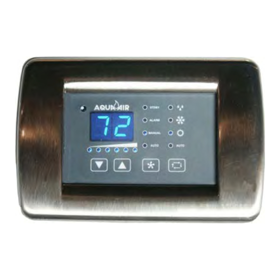
The TWWS Thermostat is comprised of the following main components: Display Panel ( TWWS-01 ) Display Cable ( TSWDC-15 ) Power Module Box ( TSVW-02 ) Room Air Sensor ( TW2-SENSOR-07 ) Water Sensor ( TW2-SENSOR-07 ) Display Panel The TSV-01 Display Panel is the user interface with the TSVW Thermostat and the TWWS-01 Display Panel is the user interface with the TWWS Thermostat. -
Page 7: Display Panel Feature Descriptions
Features of the TSV-01 and TWWS-01 Display Panel are: MODE BUTTON - The Mode Button is used to select one of the four operating modes and standby (off) mode. Pressing and releasing the Mode Button will advance you to the next mode. Continue to do this until you have reached the desired mode. -
Page 8: Power Module Box
100°F+ LED - Indicates that the actual temperature displayed is in excess of 100° F. Add the value displayed to 100 to get the actual temperature. If the 100°F LED is lit and the display shows 10 then the actual temperature would be 110°F. MAIN DISPLAY - This is a 2 digit, 7 segment LED display. -
Page 10: Pc Board Jumpers
POWER MODULE PC BOARD JUMPERS Jumper Description Type Specification Notes Chillwater / Direct Wire C/W: Jumper Cut Do not cut with Expansion Selection D/X: Jumper Not Cut power applied to board. Heater Relay Test 3 pos. Install jumper in positions 1 & 2 to energize the heater Water Valve Relay 3 pos. -
Page 11: Operation Of Controls
Chillwater Operation Below are the steps necessary for the basic operation of the control. Entering the Cooling Mode Press and release the Mode Button (1) until the Cooling Mode LED (15) is lit. Entering the Heating Mode Press and release the Mode Button (1) until the Heating Mode LED (16) is lit. Automatic (Auto) Cool / Heat Mode Press and release the Mode Button (1) until the Auto LED (17) is lit Entering the Dehumidification Mode... -
Page 12: Programming Mode
Entering the Programming Mode There are currently 14 different programmable parameters in the TSVW Thermostat. All of these parameters can be changed from the Display Panel with some simple keystrokes. The Program Mode can ONLY be entered while the control is in the Standby Mode To Program the TSVW Control: Press the Mode Button until the control is in the Standby Mode which is indicated by the Standby Mode LED (11) -
Page 13: Programmable Parameter Chart
Programmable Parameters Parameter Description Default Range Number 56 - 100 High Fan Speed Limit (% of input voltage) “00." ( 100 = 00. ) P2* ** Low Fan Speed Limit (% of input voltage) 30 - 55 Unused-Reserved for future applications Temperature Sensor Calibration -10°... -
Page 14: Fault Codes
FAULT CODES Code Description Display cable damaged. Check to see if the cable has been cut or otherwise damaged. Low Voltage Input to Power Module Box. Check your incoming voltage to the Power Module Box and verify that it is within +/-10% of the rated voltage Air Sensor Failure or Disconnected. -
Page 17: Fan Speed Process Diagram
FAN OPERATION & SPEED SELECTION CYCLING MODE HEATING COOLING TIMER > b2 AUTO MODE DELTA < 1 DELTA > 6 PROGRAMMED SPEED = 1 SPEED = 6 SPEED = DELTA FAN OFF SPEED Normal Fan Operation DELTA = Abs( Tair - Tset ) Reverse Fan Operation DELTA = Abs[ Abs( Tair - Tset) - 6 ]... -
Page 18: Cooling Mode Process Diagram
COOLING MODE COOL PROBE Tair>(Tset+1) VALVE (Tair-Twater) < (To-8) MIN FAN SPEED (Tair-Twater) < To MANUAL SPEED VALVE OFF VALVE OFF VALVE ON SELECTED FAN SPEED Tair < ( Tset - 1) To = Ambient air to Chillwater Temperature Differential A9... -
Page 19: Heating Mode Process Diagram
HEATING MODE HEAT PROBE Tair < (Tset-1) VALVE (Twater-Tair) > (To-8) MIN FAN SPEED (Twater-Tair) > To MANUAL SPEED VALVE OFF VALVE OFF VALVE ON SELECTED FAN SPEED Tair > ( Tset - 1) To = Ambient air to Chillwater Temperature Differential A9... -
Page 20: Heater Process Diagram
ELECTRIC HEATER ELECTRIC HEAT HEATING VALVE ? (Twater-Tair) > (To+7) HEATER OFF HEATER OFF HEATER ON To = Ambient air to Chillwater Temperature Differential A9... -
Page 21: Auto Mode Process Diagram
AUTO MODE AUTO HEAT HEAT COOL COOL (Tair - Tset) < -2 (Tair - Tset) > 2 COOLING MODE HEATING MODE COOLING MODE... -
Page 22: Dehumidification Process Diagram
DEHUMIDIFICATION MODE DEHUMIDIFICATION MODE SELECTING DEHUMIDIFICATION WAIT 1 MINUTE FAN ON WAIT 30 MINUTES COOLING CYCLE WAIT 1 HOUR or until ( Tair - Tset ) < -2 WAIT 4 HOURS...
Need help?
Do you have a question about the Sapphire TSVW and is the answer not in the manual?
Questions and answers