Table of Contents
Advertisement
Quick Links
Advertisement
Table of Contents

Related Manuals for Aqua-Air Tempwise 2001


Summary of Contents for Aqua-Air Tempwise 2001
- Page 1 Aqua-Air Tempwise 2001 Direct Expansion Digital Thermostat Operating Manual Aqua-Air Manufacturing division of the James D. Nall Co., Inc. 1050 East 9th Street Hialeah, FL 33010 U.S.A. Phone (305) 884-8363 Fax (305) 883-8549 Email: support@aquaair.com...
-
Page 2: Table Of Contents
Tempwise 2001 Direct Expansion Digital Thermostat Manual Tempwise 2001 Direct Expansion Digital Thermostat Aqua-Air Manufacturing 1050 East 9th Street Hialeah, Florida 33010 U.S.A. Contents Introduction ............1 Basic Operation . -
Page 3: Introduction
The Tempwise 2001 Control is designed for use with Aqua-Air Direct Expansion, reverse cycle Air Conditioning Systems. The Tempwise 2001 has a universal power supply that operates on 115V or 230V, 50 or 60 Hz AC power. The Tempwise 2001 includes the following standard and optional features:... -
Page 4: Basic Operation
Tempwise 2001. Read This Manual Completely Before Proceeding! If you require assistance prior to or during the installation of the Tempwise 2001 call Aqua-Air at (305) 884-8363 or Fax your questions to Aqua-Air at (305) 883-8549. The Tempwise 2001 is covered under existing Aqua-Air Manufacturing Warranty Policy. - Page 5 Mode Tempwise 2001 will maintain a two degrees Fahrenheit (2 temperature variation. A four degree swing is required to cause the unit to shift to the opposite mode. Once in a given mode, heating or cooling, Tempwise 2001 will maintain a two degree differential.
-
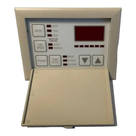
Page 6: Operator Controls And Display Panel
During the humidity cycle the water valve LED is lit while the system is cooling. MEMORY The Tempwise 2001 has nonvolatile memory which requires no batteries or any form of backup power. When power is lost the operating parameters are retained indefinitely. - Page 7 MODE BUTTON - The mode button is used to select one of the four operating modes. Press and release the mode button and the Tempwise 2001 will advance to the next mode. Continue to press and release the Mode button until the desired operating mode is reached.
- Page 8 Tempwise 2001 Direct Expansion Digital Thermostat Manual TEMP SELECT BUTTON - Press and release the Temp Mode Button to view inside air temperature, outside air temperature (optional) or the set point. The appropriate LED, Inside, Outside or Set Point will be lit indicating which temperature is being displayed.
-
Page 9: Dual Button Functions
Tempwise 2001 Direct Expansion Digital Thermostat Manual FAN SPEED BAR GRAPH - There are six (6) individual fan speed LED's in the Fan Speed Bar Graph. Each LED represents one (1) fan speed. Low fan speed (1) is indicated by illuminating the first LED. High fan speed is indicated by illuminating all six (6) LED's. -
Page 10: Modes Of Operation
MODES OF OPERATION Off Mode When the Tempwise 2001 is in the Off mode, all control outputs are turned off. Program parameters and user settings are saved in nonvolatile memory. The program mode can only be accessed from the Off mode. - Page 11 Tempwise 2001 Direct Expansion Digital Thermostat Manual Heating Only Mode When the “Heat” LED is on, only the heating systems are selected and operated as required. Should the temperature rise above the set point, the system will not automatically switch to the cooling mode. Heating only is supplied for customers that require the system to not automatically switch from the heating to the cooling mode.
-
Page 12: Fan Modes
The program mode allows the system to operate as efficiently as possible under all conditions. The Tempwise 2001 is shipped with factory programmable default settings which are stored in permanent memory and can be recalled at any time. - Page 13 The characters "P" then "P1" followed by the parameter setting, appear in the display. The Tempwise 2001 control is now in the program mode. Exit the program mode, to the off mode, by pressing and releasing the power button.
- Page 14 There are two methods to exit the Program mode. Press the power button and the Tempwise 2001 control will return to the Off mode. Not pressing any buttons or attempting any program changes for sixty (60) seconds will allow the control to exit the Program mode to the Off mode.
-
Page 15: Programming
Tempwise 2001 Direct Expansion Digital Thermostat Manual PROGRAMMING Programmable Parameters There are eighteen (18) programmable parameter locations with their Factory Default Settings listed in this section. The table below indicates what these parameters are, along with the permitted values and the original Factory Default Settings. - Page 16 Tempwise 2001 Direct Expansion Digital Thermostat Manual P-1: High Fan Limit The upper fan speed limit can be tailored to suit various motors and operating conditions. The high fan limit is adjusted with the system installed and operational. The range of values are 56 through 85 and represent arbitrary units.
- Page 17 P-7: De-Icing Cycle The Tempwise 2001 is equipped with a De-Icing Cycle to prevent ice build up on the evaporator coil during extended periods of cooling operation. Installation variables such as grille sizes, length of ducting, insulation R factors and ambient temperatures determine the cooling run time required to achieve set point.
- Page 18 Tempwise 2001 Direct Expansion Digital Thermostat Manual is flashed in the display. The factory default is Off, no pump sentry installed. P-9: Display Brightness Control The display brightness can be adjusted to suit ambient cabin lighting conditions. The allowed settings are four (4) to thirteen (13), with four (4) being the dimmest and thirteen (13) the brightest.
- Page 19 The program parameters listed on page nine may be altered by Aqua-Air Manufacturing, the installing dealer or the end user. Once new defaults are entered (see page 7, dual button functions) and memorized the new defaults will be reset.
-
Page 20: Fail Safe And Fault Handling Codes
10 of this manual. FAIL-SAFE AND FAULT HANDLING CODES When a fault is detected Tempwise 2001 will display one of the following Mnemonic fault codes: HPF...Indicates high Freon pressure. Fifteen (15) second Delay... Ignored in Heat Mode. - Page 21 Tempwise 2001 Direct Expansion Digital Thermostat Manual Failsafe Action Description of Action Taken Level All Protection FAILSAFE PROTECTION LEVELS TURNED OFF: Turned Off Air Sensor Fault: Heating/Cooling Immediately Suspended; Normal Operation Not Resumed Until Fault is Cleared. Air Sensor Fault Code "Flashing Display"...
-
Page 22: Factory Self Tests
AUTOMATED FACTORY-SELF TEST PROGRAM Self-Test Mode The Tempwise 2001 software contains a self-test program to facilitate factory testing of the entire air-conditioning system. Once the self-test mode is activated, the test cycle will continue until the AC power is interrupted or the on/off button is pressed once which returns the system to the off mode. - Page 23 Aqua Air Manufacturing. Service History Tempwise 2001 will record and remember the last eight (8) service problems or service faults detected. Each time a fault is detected, a one hour timer is started. During that hour the same recurring fault will not be recorded.
-
Page 24: Special Hardware Instructions
Optional Outside Air Sensor. Pump Sentry Option Tempwise 2001 can be equipped with an optional temperature sensor that is used to monitor condenser coil temperature. The sensor is plugged into the outside air sensor jack and parameter P-8 programmed for a temperature between 100 and 150 F, depending on the seawater temperature and the system type. - Page 25 Valve, Auxiliary Fan and Heater. Should any of these outputs fall, the output can be forced On by moving the jumper to the position indicated below. CAUTION! Allowing the Tempwise 2001 to operate with any or all of the outputs forced On while unattended can cause serious damage to the air conditioning system and/or vessel.
-
Page 26: Specifications
Tempwise 2001 Direct Expansion Digital Thermostat Manual Specifications SET POINT RANGE ......... . . 55 F - 85 TEMPERATURE RANGE DISPLAYED . - Page 27 Tempwise 2001 Direct Expansion Digital Thermostat Manual Cable Lengths Display 15' std. Optional to 50' Air Sensor 7' std. Optional to 50' Water Sensor 7' std. Optional to 50' System Inputs Inside Air Temperature Sensor Water Inlet Temperature Sensor NOTE: Maximum length of display cable is fifty (50) feet. Sensor cable lengths should be limited to 50 feet.
-
Page 28: Trouble Shooting Guide
Basic System Start-up Problems PROBLEM PROBABLE CAUSE SOLUTIONS • No lights in the display and the • AC breaker is not turned on or • Check for AC power at circuit system does not heat or cool. AC power is not available. breaker. - Page 29 • The system runs but there is no • The seawater valve is closed. • Open the seawater valve. c o o lin g h e a t in g , t h e • The seawater strainer is clogged. •...
- Page 30 Advanced Tempwise 2001 System Problems PROBLEM PROBABLE CAUSE SOLUTIONS • System runs continuously and is • Set-point temperature set too • Raise the set point to the 68 not able to achieve set-point. low. F range. • Low Refrigerant charge.
- Page 31 • The AC breaker trips when • M u l t i p l e s t a g e c h i l l e r • Enter the programming mode switching from shore to ships compressor time delays are not and set the staging delay at least set, or are all set at he same 5 seconds apart.
- Page 32 Tempwise 2001 Stuck Button Chart Stuck Button Display Behavior POWER Display will indicate “888" on Power-Up and operate in the Self Test Mode from Both the On and Off Modes. SELECT The display will enter the trouble log... VIEW HISTORY MODE. The last fault logged will be displayed, whether you are in the On or Off mode.
- Page 33 Tempwise 2001 Display Cable Troubleshooting Guide Display Problem Possible Causes No display and the buttons will not work. - The cable is assembled backwards. - Pin 1 is open - Pin 3 is open No buttons, no display but the fan is running.
Need help?
Do you have a question about the Tempwise 2001 and is the answer not in the manual?
Questions and answers