Table of Contents
Advertisement
Quick Links
Advertisement
Table of Contents

Related Manuals for Asus N3150M-E


Summary of Contents for Asus N3150M-E
- Page 1 N3150M-E N3050M-E...
- Page 2 Product warranty or service will not be extended if: (1) the product is repaired, modified or altered, unless such repair, modification of alteration is authorized in writing by ASUS; or (2) the serial number of the product is defaced or missing.
-
Page 3: Table Of Contents
Contents Safety information ...................... iv About this guide ......................iv Package contents ....................... vi N3150M-E / N3050M-E specifications summary ............vi Chapter 1: Product introduction Before you proceed ..................1-1 Motherboard overview ................. 1-2 Central Processing Unit (CPU) ..............1-4 System memory .................... -
Page 4: Safety Information
Safety information Electrical safety • To prevent electrical shock hazard, disconnect the power cable from the electrical outlet before relocating the system. • When adding or removing devices to or from the system, ensure that the power cables for the devices are unplugged before the signal cables are connected. If possible, disconnect all power cables from the existing system before you add a device. -
Page 5: Conventions Used In This Guide
Refer to the following sources for additional information and for product and software updates. ASUS websites The ASUS website provides updated information on ASUS hardware and software products. Refer to the ASUS contact information. Optional documentation Your product package may include optional documentation, such as warranty flyers, that may have been added by your dealer. -
Page 6: Package Contents
** Only for N3050M-E 2 x DIMM DDR3 1600/1066 MHz, Max 8GB, non-ECC, un-buffered memory Memory Dual-channel memory architecture * Refer to www.asus.com for the latest Memory QVL (Qualified Vendors List). Graphics Integrated Graphics Processor- Intel HD Graphics support ®... -
Page 7: Asus Exclusive Features
64Mb Flash ROM, UEFI AMI BIOS, PnP, DMI2.0, WfM2.0,SM BIOS 2.7, BIOS features ACPI 2.0a, Multi-language BIOS, ASUS EZ Flash 2, ASUS CrashFree BIOS 3, My Favorites, Quick Note, Last Modified log, F12 PrintScreen, F3 Shortcut functions and ASUS DRAM SPD (Serial Presence Detect) - Page 8 Wfm 2.0, DMI 2.0, WOL by PME, PXE Operating System Windows 8.1 64-bit ® Drivers Support DVD ASUS utilities EZ Update Anti-virus software (OEM version) Form factor m-ATX Form Factor, 8.9” x 7.0” (22.6cm x 17.8cm) Specifications are subject to change without notice. viii...
-
Page 9: Chapter 1: Product Introduction
Unplug the power cord from the wall socket before touching any component. • Before handling components, use a grounded wrist strap or touch a safely grounded object or a metal object, such as the power supply case, to avoid damaging them due to static electricity. • Hold components by the edges to avoid touching the ICs on them. • Whenever you uninstall any component, place it on a grounded antistatic pad or in the bag that came with the component. • Before you install or remove any component, ensure that the ATX power supply is switched off or the power cord is detached from the power supply. Failure to do so may cause severe damage to the motherboard, peripherals, or components. ASUS N3150M-E / N3050M-E... -
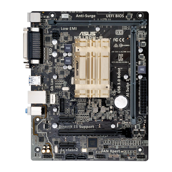
Page 10: Motherboard Overview
The edge with external ports goes to the rear part of the chassis as indicated in the image below. 1.2.2 Screw holes Place six screws into the holes indicated by circles to secure the motherboard to the chassis. Do not overtighten the screws! Doing so can damage the motherboard. N3150M-E N3050M-E Place this side towards the rear of the chassis Chapter 1: Product introduction... -
Page 11: Motherboard Layout
Connectors/Jumpers/Slots/LED Page ATX power connectors (24-pin EATXPWR, 4-pin ATX12V)) 1-12 CPU and chassis fan connectors (4-pin CPU_FAN, 4-pin CHA_FAN) 1-12 DDR3 DIMM sockets Intel Celeron Quad Core Processor N3150* / Intel Celeron Dual Core Processor ® ® N3050** * N3150M-E with Intel SOC N3150 / ** N3050M-E with Intel SOC N3050 System panel connector (10-1 pin F_PANEL) 1-15 Clear RTC RAM (2-pin CLRTC) Speaker connector (4-pin SPEAKER) 1-14 COM port connector (10-1 pin COM) 1-11 Serial ATA 6.0Gb/s connectors (7-pin SATA6G_1/2) 1-13 10. USB 2.0 connector (10-1 pin USB_E34) 1-13 11. Front panel audio connector (10-1 pin AAFP) 1-11 12. -
Page 12: Central Processing Unit (Cpu)
Attention: If only one N3050M-E DDR3/-L memory module is Channel A DIMM_A1 to be installed, be sure to install it in DIMM_A1. Channel B DIMM_B1 N3150M-E / N3050M-E 240-pin DDR3 DIMM sockets 1.4.2 Memory configurations You may install 1GB, 2GB, 4GB, and 8GB unbuffered non-ECC DDR3 DIMMs into the DIMM sockets. • You may install varying memory sizes in Channel A and Channel B. The system maps the total size of the lower-sized channel for the dual-channel configuration. Any excess memory from the higher-sized channel is then mapped for single-channel operation. -
Page 13: Installing A Dimm
• Due to the memory address limitation on 32-bit Windows OS, when you install 4GB ® or more memory on the motherboard, the actual usable memory for the OS can be about 3GB or less. For effective use of memory, we recommend that you do any of the following: Install a maximum of 3GB system memory if you are using a 32-bit Windows® Use a 64-bit Windows OS if you want to install 4GB or more memory on the ® motherboard. • This motherboard does not support DIMMs made up of 512Mb (64MB) chips or less. • The default memory operation frequency is dependent on its Serial Presence Detect (SPD), which is the standard way of accessing information from a memory module. Under the default state, some memory modules for overclocking may operate at a lower frequency than the vendor-marked value. To operate at the vendor-marked or at a higher frequency, refer to section 2.5 Ai Tweaker menu for manual memory frequency adjustment. • For system stability, use a more efficient memory cooling system to support a full memory load (2 DIMMs) or overclocking condition. • Refer to www.asus.com for the latest Memory QVL (Qualified Vendors List). 1.4.3 Installing a DIMM ASUS N3150M-E / N3050M-E... -
Page 14: Expansion Slots
To remove a DIMM Expansion slots In the future, you may need to install expansion cards. The following sub-sections describe the slots and the expansion cards that they support. Unplug the power cord before adding or removing expansion cards. Failure to do so may cause you physical injury and damage motherboard components. 1.5.1 Installing an expansion card To install an expansion card: Before installing the expansion card, read the documentation that came with it and make the necessary hardware settings for the card. Remove the system unit cover (if your motherboard is already installed in a chassis). -
Page 15: Configuring An Expansion Card
Realtek 8111H Controller – – shared – – – – – XHCI Controller – – – – shared – – – HD Audio Controller – – – – – – shared – SATA Controller – – – – shared – – – ASUS N3150M-E / N3050M-E... -
Page 16: Headers
Headers Clear RTC RAM (2-pin CLRTC) This header allows you to clear the Real Time Clock (RTC) RAM in CMOS. You can clear the CMOS memory of date, time, and system setup parameters by erasing the CMOS RTC RAM data. The onboard button cell battery powers the RAM data in CMOS, which include system setup information such as system passwords. N3150M-E N3050M-E CLRTC PIN 1 N3150M-E / N3050M-E Clear RTC RAM To erase the RTC RAM: Turn OFF the computer and unplug the power cord. Use a metal object such as a screwdriver to short the two pins. Plug the power cord and turn ON the computer. Hold down the <Del> key during the boot process and enter BIOS setup to re- enter data. • If the steps above do not help, remove the onboard battery and short the two pins again to clear the CMOS RTC RAM data. After clearing the CMOS, reinstall the battery. • You do not need to clear the RTC when the system hangs due to overclocking. For system failure due to overclocking, use the CPU Parameter Recall (C.P.R.) feature. Shut down and reboot the system, then the BIOS automatically resets parameter settings to default values. -
Page 17: Connectors
Linked ORANGE 100Mbps connection Orange (Blinking) Data activity GREEN 1Gbps connection LAN port Orange (Blinking Ready to wake up then steady) from S5 mode Line In port (light blue). This port connects to the tape, CD, DVD player, or other audio sources. Line Out port (lime). This port connects to a headphone or a speaker. In the 4.1, 5.1 and 7.1-channel configurations, the function of this port becomes Front Speaker Out. Microphone port (pink). This port connects to a microphone. Refer to the audio configuration table for the function of the audio ports in 2.1, 4.1, 5.1, or 7.1-channel configuration. ASUS N3150M-E / N3050M-E... - Page 18 Audio 2.1, 4.1, 5.1 or 7.1-channel configuration Headset Port 4.1-channel 5.1-channel 7.1-channel 2.1-channel Light Blue Line In Rear Speaker Out Rear Speaker Out Rear Speaker Out (Rear panel) Lime (Rear panel) Line Out Front Speaker Out Front Speaker Out Front Speaker Out Pink (Rear panel) Mic In Mic In Bass/Center Bass/Center Lime (Front panel) — — — Side Speaker Out To configure a 7.1-channel audio output: •...
-
Page 19: Internal Connectors
N3050M-E AAFP PIN 1 PIN 1 HD-audio-compliant Legacy AC’97 pin definition compliant definition N3150M-E / N3050M-E Front panel audio connector • We recommend that you connect a high-definition front panel audio module to this connector to avail of the motherboard’s high-definition audio capability. • If you want to connect a high-definition front panel audio module to this connector, set the Front Panel Type item in the BIOS setup to [HD]. If you want to connect an AC'97 front panel audio module to this connector, set the item to [AC97]. By default, this connector is set to [HD]. See section 2.5.6 Onboard Devices Configuration for details. - Page 20 +5 Volts Power OK -5 Volts +5 Volts +5 Volts PSON# +3 Volts -12 Volts +3 Volts +3 Volts PIN 1 N3150M-E / N3050M-E ATX power connectors • For a fully configured system, we recommend that you use a power supply unit (PSU) that complies with ATX 12 V Specification 2.0 (or later version) and provides a minimum power of 350 W. • DO NOT forget to connect the 4-pin ATX +12V power plug. Otherwise, the system will not boot up. • If you are uncertain about the minimum power supply requirement for your system, refer to the Recommended Power Supply Wattage Calculator at http://support.asus. com/PowerSupplyCalculator/PSCalculator.aspx?SLanguage=en-us for details.
- Page 21 This USB connector complies with USB 2.0 specification that supports up to 480 Mbps connection speed. USB_E34 N3150M-E N3050M-E PIN 1 N3150M-E / N3050M-E USB2.0 connector Never connect a 1394 cable to the USB connector. Doing so will damage the motherboard! The USB module cable is purchased separately. Serial ATA 6.0Gb/s connectors (7-pin SATA6G_1/2) These connectors connect to Serial ATA 6.0 Gb/s hard disk drives via Serial ATA 6.0 Gb/s signal cables. N3150M-E...
- Page 22 Speaker connector (4-pin SPEAKER) The 4-pin connector is for the chassis-mounted system warning speaker. The speaker allows you hear system beeps and warnings. N3150M-E N3050M-E SPEAKER PIN 1 N3150M-E / N3050M-E Speaker Out connector USB 3.0 connector (20-1 pin USB3_34) This connector allows you to connect a USB 3.0 module for additional USB 3.0 front or rear panel ports. With an installed USB 3.0 module, you can enjoy all the benefits of USB 3.0 including faster data transfer speeds of up to 5Gbps, faster charging time for USB-chargeable devices, optimized power efficiency, and backward compatibility with USB 2.0. USB3_34 N3150M-E IntA_P2_D+ IntA_P1_D+ IntA_P2_D- IntA_P1_D-...
-
Page 23: System Panel Connector
System panel connector (10-1 pin F_PANEL) This connector supports several chassis-mounted functions. F_PANEL +PWR LED- PWR BTN N3150M-E N3050M-E PIN 1 +HDD_LED- RESET N3150M-E / N3050M-E System panel connector • System power LED (2-pin PWRLED) This 2-pin connector is for the system power LED. Connect the chassis power LED cable to this connector. The system power LED lights up when you turn on the system power, and blinks when the system is in sleep mode. • Hard disk drive activity LED (2-pin +HDLED) This 2-pin connector is for the HDD Activity LED. Connect the HDD Activity LED cable to this connector. The HD LED lights up or flashes when data is read from or written to the HDD. -
Page 24: Software Support
8.1 64-bit. Always install the latest OS version and ® corresponding updates to maximize the features of your hardware. Motherboard settings and hardware options vary. Refer to your OS documentation for detailed information. 1.8.2 Support DVD information The Support DVD that comes with the motherboard package contains the drivers, software applications, and utilities that you can install to avail all motherboard features. The contents of the Support DVD are subject to change at any time without notice. Visit the ASUS website at www.asus.com for updates. To run the Support DVD Place the Support DVD into the optical drive. If Autorun is enabled in your computer, the DVD automatically displays the Specials screen which contains the unique features of ASUS motherboard. Click Drivers, Utilities, Manual, and Contact tabs to display their respective menus. The following screen is for reference only. Click an icon to display Support DVD/motherboard information... -
Page 25: Chapter 2: Bios Information
Managing and updating your BIOS Save a copy of the original motherboard BIOS file to a USB flash disk in case you need to restore the BIOS in the future. Copy the original motherboard BIOS using the ASUS Update utility. -
Page 26: Asus Ez Flash
2.1.2 ASUS EZ Flash 2 The ASUS EZ Flash 2 feature allows you to update the BIOS without using an OS‑based utility. Before you start using this utility, download the latest BIOS file from the ASUS website at www.asus.com. To update the BIOS using EZ Flash 2: Insert the USB flash disk that contains the latest BIOS file to the USB port. -
Page 27: Asus Crashfree Bios 3 Utility
2.1.3 ASUS CrashFree BIOS 3 utility The ASUS CrashFree BIOS 3 is an auto recovery tool that allows you to restore the BIOS file when it fails or gets corrupted during the updating process. You can restore a corrupted BIOS file using the motherboard support DVD or a USB flash drive that contains the updated BIOS file. - Page 28 ENTER to select boot device ESC to boot using defaults P2: ST3808110AS (76319MB) aigo miniking (250MB) UEFI: (FAT) ASUS DRW-2014L1T(4458MB) P1: ASUS DRW-2014L1T(4458MB) UEFI: (FAT) aigo miniking (250MB) Enter Setup When the booting message appears, press <Enter> within five (5) seconds to enter FreeDOS prompt.
- Page 29 DO NOT shut down or reset the system while updating the BIOS to prevent system boot failaure. Ensure to load the BIOS default settings to ensure system compatibility and stability. Select the Load Optimized Defaults item under the Exit BIOS menu. See section 2.10 Exit Menu for details. ASUS N3150M-E / N3050M-E...
-
Page 30: Bios Setup Program
The BIOS setup screens shown in this section are for reference purposes only, and may not exactly match what you see on your screen. • Visit the ASUS website at www.asus.com to download the latest BIOS file for this motherboard. •... - Page 31 Advanced mode Loads optimized bootable menus default settings devices Selects the boot Saves the changes device priority and resets the system The boot device options vary depending on the devices you installed to the system. ASUS N3150M-E / N3050M-E 2‑7...
-
Page 32: Advanced Mode
2.2.2 Advanced Mode The Advanced Mode provides advanced options for experienced end‑users to configure the BIOS settings. The figure below shows an example of the Advanced Mode. Refer to the following sections for the detailed configurations. To access the EZ Mode, click EzMode(F7) or press <F7>. Quick Note Hot keys MyFavorite... -
Page 33: Menu Bar
You can only use the alphanumeric characters to enter your notes. Hot keys This button above the menu bar contains the navigation keys for the BIOS setup program. Use the navigation keys to select items in the menu and change the settings. ASUS N3150M-E / N3050M-E... -
Page 34: My Favorites
Scroll bar A scroll bar appears on the right side of a menu screen when there are items that do not fit on the screen. Press the Up/Down arrow keys or <Page Up> / <Page Down> keys to display the other items on the screen. General help At the top right corner of the menu screen is a brief description of the selected item. -
Page 35: Adding Items To My Favorites
You cannot add the following items to My Favorite items: • User‑managed items such as language and boot order Click Exit (ESC) or press <esc> key to close Setup Tree Map screen. Go to My Favorites menu to view the saved BIOS items. ASUS N3150M-E / N3050M-E 2-11... -
Page 36: Main Menu
Main menu The Main menu screen appears when you enter the Advanced Mode of the BIOS Setup program. The Main menu provides you an overview of the basic system information, and allows you to set the system date, time, language, and security settings. 2.4.1 Language [English] Allows you to choose the BIOS language version from the options. -
Page 37: Administrator Password
To clear the user password, follow the same steps as in changing a user password, but press <Enter> when prompted to create/confirm the password. After you clear the password, the User Password item on top of the screen shows Not Installed. ASUS N3150M-E / N3050M-E 2‑13... -
Page 38: Advanced Menu
Advanced menu The Advanced menu items allow you to change the settings for the CPU and other system devices. Be cautious when changing the settings of the Advanced menu items. Incorrect field values can cause the system to malfunction. 2.5.1 OCMR Over Voltage Control The items in this menu allows you to manage the OCMR Over Voltage Control settings. -
Page 39: Ppm Configuration
[Enabled] Enables the IGD Turbo feature. [Disabled] Disables the IGD Turbo feature. Primary Display [Auto] Allows you to select which of the IGD/PCIe Graphics device should be the Primary Display. Configuration options: [Auto] [IGD] [PCIe] ASUS N3150M-E / N3050M-E 2-15... -
Page 40: Sata Configuration
iGPU Memory [64M] Allows you to select the pre‑allocated or fixed graphics memory size for DVMT 5.0 used by the IGD. Configuration options: [32M] [64M] [96M] [128M] [160M] [192M] [224M] [256M] [288M][320M] [352M] [384M] [416M] [448M] [480M] [512M] PUNIT Power Configuration [Enabled] Enables or disables the Punit Power configuration. -
Page 41: Network Stack
The USB devices can be used only for the BIOS setup program. [Auto] Allows the system to detect the presence of USB devices at startup. If detected, the USB controller legacy mode is enabled. If no USB device is detected, the legacy USB support is disabled. ASUS N3150M-E / N3050M-E 2‑17... -
Page 42: Onboard Devices Configuration
xHCI Hand-off [Disabled] [Enabled] BIOS supports xHCI for the operating system without xHCI support. [Disabled] xHCI drivers support xHCI for the operating system with xHCI support. USB Single Port Control This item allows you to enable or disable the individual USB ports. Refer to section 1.2.3 Motherboard layout for the location of the USB ports. -
Page 43: Parallel Port Configuration
PCIE LAN cards. Configuration options: [Disabled] [Enabled] Power On By RTC [Disabled] [Disabled] Disables RTC to generate a wake event. [Enabled] When set to [Enabled], the items RTC Alarm Date (Days) and Hour/ Minute/Second will become user‑configurable with set values. ASUS N3150M-E / N3050M-E 2-19... -
Page 44: Monitor Menu
Monitor menu The Monitor menu displays the system temperature/power status, and allows you to change the fan settings. Scroll down to display the other BIOS items. 2.6.1 CPU/ MB Temperature [xxxºC/xxxºF]/ [Ignore] The onboard hardware monitor automatically detects and displays the CPU and motherboard temperatures. - Page 45 [Silent] Sets to [Silent] to minimize the fan speed for quiet chassis fan operation. [Turbo] Sets to [Turbo] to achieve maximum chassis fan speed. [Manual] Sets to [Manual] to assign detailed fan speed control parameters. ASUS N3150M-E / N3050M-E 2-21...
-
Page 46: Boot Menu
The following four items appear only when you set Chassis Fan Profile to [Manual]. Chassis Fan Upper Temperature [70] Use the <+> and <‑> keys to adjust the upper limit of the Chassis temperature. The values range from 40ºC to 75ºC. Chassis Fan Max. - Page 47 Accelerates the boot speed on the next boot after AC power loss. 2.7.2 Boot Logo Display [Auto] [Auto] Adjusts logo automatically based on Windows display requrements. ® [Full Screen] Maximize the boot logo size. [Disabled] Hide the logo during POST. ASUS N3150M-E / N3050M-E 2‑23...
- Page 48 2.7.5 Option ROM Messages [Enabled] [Enabled] The third‑party ROM messages will be displayed during POST. [Disabled] Disables the ROM messages and displays only the ASUS logo during POST. 2.7.6 INT19 Trap Response [Disabled] [Immediate] Allows the option ROM to quickly trap Interrupt 19.
-
Page 49: Secure Boot
Unloaded mode to loaded mode. Clear Secure Boot keys This item appears only when you load the default Secure Boot keys. This item allows you to clear all the previously applied Secure Boot keys. ASUS N3150M-E / N3050M-E 2-25... - Page 50 Save Secure Boot Keys This item allows you to save all the Secure Boot keys to a USB storage device. PK Management The Platform Key (PK) locks and secures the firmware from any non‑permissible changes. The system verifies the PK before your system enters the OS. Delete PK Allows you to delete the PK from your system.
-
Page 51: Boot Option Priorities
OS in Safe Mode, press <F8 > after POST (Windows 8 not supported). • To select the boot device during system startup, press <F8> when ASUS Logo appears. 2.7.12 Boot Override These items displays the available devices. The number of device items that appears on the screen depends on the number of devices installed in the system. -
Page 52: Tool Menu
<Enter> to display the submenu. 2.8.1 ASUS EZ Flash 2 Utility Allows you to run ASUS EZ Flash 2. Press [Enter] to launch the ASUS EZ Flash 2 screen. For more details, see section 2.1.2 ASUS EZ Flash 2. 2.8.2 ASUS Overclocking Profile This item allows you to store or load multiple BIOS settings. -
Page 53: Asus Spd Information
<Esc>, a confirmation window appears. Select OK to discard changes and exit. Launch EFI Shell from USB drives This option allows you to attempt to launch the EFI Shell application (shellx64.efi) from one of the available USB devices. ASUS N3150M-E / N3050M-E 2-29... - Page 54 2‑30 Chapter 2: Getting started...
-
Page 55: Appendices
: (1) cet appareil ne doit pas provoquer d’interférences et (2) cet appareil doit accepter toute interférence, y compris celles susceptibles de provoquer un fonctionnement non souhaité de l’appareil. ASUS N3150M-E / N3050M-E... -
Page 56: Canadian Department Of Communications Statement
ASUS Recycling/Takeback Services ASUS recycling and takeback programs come from our commitment to the highest standards for protecting our environment. We believe in providing solutions for you to be able to responsibly recycle our products, batteries, other components as well as the packaging materials. - Page 57 CE. das Diretivas da CE. Para mais detalhes, consulte a Declaração de Компания ASUS заявляет, что это устройство соответствует основным Conformidade CE. требованиям и другим соответствующим условиям европейских директив. Подробную информацию, пожалуйста, смотрите в декларации...
-
Page 58: Asus Contact Information
+1-510-739-3777 +1-510-608-4555 Web site http://www.asus.com/us/ Technical Support Support fax +1-812-284-0883 General support +1-812-282-2787 Online support http://www.service.asus.com/ ASUS COMPUTER GmbH (Germany and Austria) Address Harkort Str. 21-23, D-40880 Ratingen, Germany +49-2102-959931 Web site http://www.asus.com/de Online contact http://eu-rma.asus.com/sales Technical Support Telephone +49-2102-5789555... - Page 59 ASUS N3150M-E / N3050M-E...
Need help?
Do you have a question about the N3150M-E and is the answer not in the manual?
Questions and answers