Table of Contents
Advertisement
Quick Links
Advertisement
Table of Contents

Subscribe to Our Youtube Channel
Related Manuals for TDI LCR1

Summary of Contents for TDI LCR1
- Page 1 TDI International, Inc. The Technical Source! TDI LCR Smart Tweezers L - C - R Meter & Component Identifi er Models #TDI LCR1 / #TDI LCR2 / #TDI LCR4 User’s Manual TDI International, Inc. www.tdiinternational.com Phone (520) 799-8000 / Email: handtools@tdiinternational.com...
- Page 2 TDI International, Inc. The Technical Source! Page 1...
-
Page 3: Table Of Contents
TDI International, Inc. The Technical Source! TABLE OF CONTENTS Notice.............................3 Warranty............................3 Safety Precautions..........................4 Getting Started............................5 Overview............................5 Controls............................8 Power On..............................9 Menu Structures and Functions........................11 Measurement Features.........................22 Measuring Resistance..........................22 Measuring Capacitance..........................22 Measuring Inductance..........................23 Maintenance..........................24 Labelling & Verifi cation Requirements....................25 Appendix A. Specifi cations........................26 Appendix B. -
Page 4: Notice
To exercise this warranty, contact TDI International, Inc. (contact info provided on the back page of this user guide). You will be given prompt assistance and return instructions. Please send the product with shipping prepaid to the indicated service facility. -
Page 5: Safety Precautions
• Do not attempt to measure any components in-circuit when your circuit is alive • or active. To avoid possible damage to TDI LCR Smart Tweezers or to the equipment under test, follow these guidelines: • Disconnect circuit power supply and discharge all high-voltage capacitors before •... -
Page 6: Getting Started
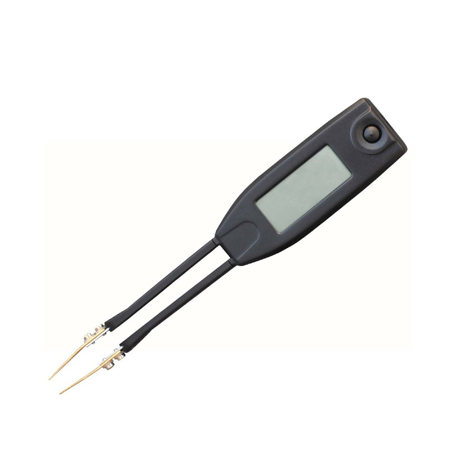
MENU STRUCTURE: Covers menu structure, system settings and features. OVERVIEW TDI LCR Smart Tweezers (ST) is a portable impedance measuring device. ST is capable of measuring resistance, capacitance or inductance over a range of more than 8 orders of magnitude. The device has a basic accuracy better than 0.2% (resistance) and operates at four test frequencies. - Page 7 TDI International, Inc. The Technical Source! HOW IT WORKS ST evaluates impedance of a component by measuring the voltage across the com- ponent and current through it. The complex ratio of voltage to current is equal to the complex impedance. The unit’s processor calculates various parameters that are dis- played i.e.
- Page 8 TDI International, Inc. The Technical Source! The output voltage is applied to the device under test through the source of imped- ance. The voltage across the device is always less than or equal to the output voltage. Source impedance values are 62.5...
-
Page 9: Controls
TDI International, Inc. The Technical Source! CONTROLS The Navigation Controller The controller is used to select a function or to change a setting of Smart Tweezers. The controller can be moved (rocked) in 4 directions (UP, DOWN, LEFT, RIGHT). Se- lection is performed by pressing along the vertical axis (PRESS). -
Page 10: Power On
TDI International, Inc. The Technical Source! POWER ON POWER-ON - To Turn the Smart Tweezers ON, press the navigation controller. Note: Once powered on, the unit will perform the last selected function. POWER-OFF - ST powers off automatically if neither a measurement is performed or the navigation controller is operated for approximately 30 seconds (default value). - Page 11 TDI International, Inc. The Technical Source! PRIMARY DISPLAY: The Primary Display is located in the middle of the screen and uses the largest font. It shows the dominant impedance parameter reading typically with 5 digits displayed. SECONDARY DISPLAY: The Secondary Display is located just above the Primary Display.
-
Page 12: Menu Structures And Functions
TDI International, Inc. The Technical Source! C+R MODE: Capacitance is shown on the Primary Display and the parallel resistance R, is shown on the Secondary Display. The units of capacitance are pF, nF or F. Re- sistance units are or k . Parallel (C<500 pF) or serial (C>500pF) equivalent circuit diagram is used. - Page 13 TDI International, Inc. The Technical Source! • Service Menu - service functions. • Measurement Menu - measurement functions and settings. • Mode Menu - measurement modes. • Setting Menu - measurement parameter settings. NAVIGATING MENUS Move the Navigation Controller UP or DOWN to move cursor to the desired menu item and PRESS it to select the item.
- Page 14 TDI International, Inc. The Technical Source! SYSTEM MENU System menu is used to access system settings and functions SOUND MENU Sound menu is used to change the sound setting for measurement confi rmation. Select ON to enable the measurement confi rmation sound.
- Page 15 TDI International, Inc. The Technical Source! DISPLAY MENU Display menu is used to change dis- play’s settings: • Select RIGHT to set “Right Handed” display mode. • Select LEFT to set “Left Handed” display mode. CONTRAST Select CONTR to adjust display con- trast.
- Page 16 TDI International, Inc. The Technical Source! SERIAL NUMBER Select S/N to display the device serial number and the fi rmware version. MEASUREMENT MENU Measurement modes and settings. MODE MENU The Mode menu is used to set the measurement mode. Select RES, IND,...
- Page 17 TDI International, Inc. The Technical Source! RESISTANCE MODE: Enables Resistance measurement mode. See section MEA- SURING FEATURES for more information. INDUCTANCE MODE: Enables Inductance measurement mode. See section MEA- SURING FEATURES for more information. CAPACITANCE MODE: Enables Capacitance measurement mode. See section MEA- SURING FEATURES for more information.
- Page 18 TDI International, Inc. The Technical Source! SETTING MENU Use this menu to set specifi c measure- ment parameter. TEST FREQUENCY MENU Use this menu to set desired test fre- quency. RDQ MENU Use this menu to set secondary display parameter.
- Page 19 TDI International, Inc. The Technical Source! RANGE MENU Use this menu to set desirable source impedance range. Default value is auto-ranging (AUTO). Note: Auto-ranging procedure starts from R2 (1kOhm) LEVEL MENU Use this menu to set desirable test sig- nal level. Default value is 1.0 Vrms.
- Page 20 TDI International, Inc. The Technical Source! TOLERANCE MENU This function is designed for component sorting. It checks whether the measured com- ponent is within preset tolerance from the reference component. The tolerance ranges available are 1%, 5%, 10% and 20% To preset a tolerance range: •...
- Page 21 TDI International, Inc. The Technical Source! One common application is to increase the accuracy of a small resistance measure- ment by storing (nulling) the test resistance (test leads shorted). Obtaining the leads offset (nulling) is also particularly important prior to making small capacitance measurements (test leads open).
- Page 22 TDI International, Inc. The Technical Source! During measurements an asterisk will appear beside the test mode indicator for which the offset has been stored indicating relative measurement. To reset (set to zero) the stored offset for a particular test mode: •...
-
Page 23: Measurement Features
TDI International, Inc. The Technical Source! MEASUREMENT FEATURES This section describes specifi c ST functions and settings. Measuring Resistance Covers Resistance Measurements Measuring Capacitance Covers Capacitance Measurements Measuring Inductance Covers Inductance Measurements Testing Diodes Describes Testing General Purpose Diodes MEASURING SMALL RESISTANCE There is some small resistance offset due to the resistance of the tweezer tips, and resistance of the contacts between the tips and DUT. -
Page 24: Measuring Inductance
TDI International, Inc. The Technical Source! Optimal Test Frequency <10000pF 10kHz 1kHz 10001pF-1 There is some small capacitance offset due to capacitance of the tips. The offset de- pends on the distance between the tips (i.e. measured component size). The offset value should be used in calculation of the actual capacitance. -
Page 25: Maintenance
TDI International, Inc. The Technical Source! ESR MEASUREMENTS Use the ESR measurements to measure the equivalent series resistance of a capacitor independent of its capacitance. Test Frequency 0.1kHz / 1kHz / 10kHz Test Signal Amplitude 0.25 / 0.5 / 1.0 Vrms Sine Wave Source Impedance 62.5... -
Page 26: Labelling & Verifi Cation Requirements
TDI International, Inc. The Technical Source! LOW BATTERY INDICATION The empty battery icon on the display indicates that device’s battery voltage is low and it should be recharged. The warning appears when the battery voltage drops below 3.55V, i.e. the batteries are about 90% depleted. The unit is still operating for a short time;... -
Page 27: Appendix A. Specifi Cations
TDI International, Inc. The Technical Source! APPENDIX A. SPECIFICATIONS TECHNICAL SPECIFICATIONS AC Test Mode Test Frequency: 1kHz, 10kHz, 120Hz, 100Hz Test Frequency Accuracy: 50 PPM (0.005%) Test Signal Level: 0.25 / 0.5 / 1.0 +/- Vrms Sine Wave Source Impedance: 62.5... - Page 28 TDI International, Inc. The Technical Source! MAXIMUM MEASUREMENT RANGES Resistance R: 0.05 to 9.9 M Capacitance C: 0.5 pF to 4999 Inductance L: 0.5 uH to 999 mH Quality Factor Q: 0.001 to 1000* Dissipation Factor D: 0.001 to 1000*...
-
Page 29: Appendix B. Default Settings
TDI International, Inc. The Technical Source! PHYSICAL SPECIFICATIONS 14.0 x 2.5 x 3.0 cm Size (3.94 x 0.9 x 1.5 in) Weight 53 Grams (0.11 lbs.) ENVIRONMENTAL CONDITIONS Operating Temperature: 0°C to 50°C Storage Temperature: -40°C to 70°C Relative Humidity: 0% to 90% (0°C to 35°C) -
Page 30: Appendix C. Accuracy Specifi Cation
TDI International, Inc. The Technical Source! Default Settings After AUTOSET Command SOUND Mode: DISPLAY Mode: No Change Contrast: No Change Readings PERIOD: 1 Sec Measurement Mode: AUTO Test Frequency Mode: AUTO Offset CALIBRATION: No Change APPENDIX C. ACCURACY SPECIFICATION RESISTANCE, IMPEDANCE. - Page 31 TDI International, Inc. The Technical Source! CAPACITANCE Range Resolution 100Hz 120Hz 1kHz 10kHz 10mF 0.001mF 2.0% +8 2.0% +8 0.5% +5 0.5% +5 1000 0.3% +3 0.3% +3 0.5% +5 0.01 0.2% +3 0.2% +3 0.2% +3 0.5% +5 0.001 0.2% +3...
- Page 32 TDI International, Inc. 3351 E. Hemisphere Loop Tucson, AZ 85706 Phone: (520) 799-8000 / Fax: (520) 799-8002 Email: handtools@tdiinternational.com / sales@tdiinternational.com Website: www.tdiinternational.com...
Need help?
Do you have a question about the LCR1 and is the answer not in the manual?
Questions and answers