
Related Manuals for Count EZCREASER

Summary of Contents for Count EZCREASER
- Page 1 4-2009 EZCREASER Version 1.6 Serial Number ___________________________ Date ___________________________________...
- Page 2 The EZ Creaser with it’s microprocessor driven transport promises many years of profitable operation. Your EZ Creaser was manufactured at Count’s headquarters in Escondido, California. We are proud to build quality equipment and stand behind our machines knowing that the quality of our product is exceeded only by the staff which supports it.
-
Page 3: Table Of Contents
TABLE OF CONTENTS (JANUARY 2007) SPECIFICATIONS…………………………………………………………………………………………….1a SAFETY PROCEDURES/CARE & MAINTENANCE.………………………………………………….1b COMPONENT IDENTIFICATION…………………………………………………………………………2 SETTING UP YOUR EZ CREASER……………………………………………………………………….3 W/ Optional Stand………………………………………………………………………3 MICROPROCESSOR CONTROLLER EZ CREASER………………………………………………….4 Transport Operation Controls……………………………………………….………5 Programming Controls (mode Selection)…………………………….……..…5 Programming for Creasing………………………………………….…….…………6 Setting up Creasing…………………………….……………………….……….……6 Batch Counter………………………………………………………………….……….7 Total Counter……………………………………………………………………………8 Double Sheet Detector………………………………………………………………8 Programming Notes…………………………………………………………………..8 DELIVERY TRAY ASSEMBLY…………………………………………………………………………….9... -
Page 4: Specifications
ELECTRICAL SPECIFICATIONS Power Requirement: 110v, 60 HZ, AC, or International 230v, 50/60HZ, AC Circuit Protection: Motor/Transformer………………………..3 AMP Circuit Breaker Microprocessor……………………………..1/4 AMP Slo-Blow Pulse Board………………………………….3 AMP Slo-Blow NOTE: Older buildings, overloaded lines, and bad grounds can affect the operation of your EZ Creaser. A dedicated line is best. OPERATING SPEEDS MODE TRANSPORT SPEED... -
Page 5: Safety Procedures/Care & Maintenance
SAFETY PROCEDURES BEFORE USE: Read through the owner’s manual. Follow instructions CAREFULLY. • NEVER use a wet area. Electric shock could occur. • Use a GROUNDED outlet and a GROUNDED circuit. Do no use ungrounded • equipment on the same circuit. Always use a dedicated line. -
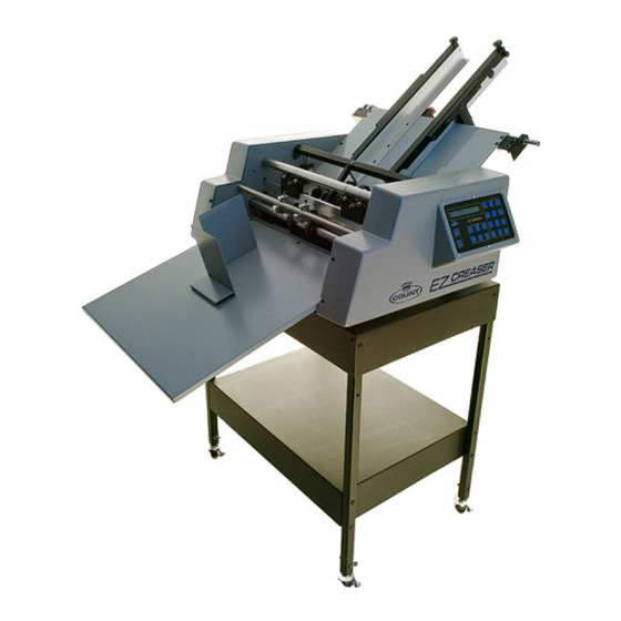
Page 6: Component Identification
COMPONENT IDENTIFICATION Feed Rail Assembly Feed Table Assembly Perf and Score Assemblies Crease Bar Microprocessor Paper Stop Delivery Tray Machine Stand REFERENCES Machine Stand Pg. 3 Microprocessor Pg. 4 Feed Table Assembly Pg. 9 Delivery Tray Pg. 9 Perf and Score Assemblies Pg. -
Page 7: Setting Up Your Ez Creaser
SETTING UP YOUR EZ CREASER STAND ( optional 1. Open top half of box and remove components. 2. Assemble stand. 3. Place machine on stand as shown below. 4. Unscrew feed rail guide shaft, slide shaft out. Place feed rails on feed table and slide shaft back in going through feed rail guide brackets. -
Page 8: Microprocessor Controller Ez Creaser
A countdown sequence from 9 to 0 will appear. If a number is missing from the sequence this indicates a failure in a component. If this occurs, contact the Count service department for further details. At the display of “EZ Creaser” the microprocessor is clear and ready to accept the entries. -
Page 9: Transport Operation Controls
• • • • Enter/Yes: Stores input information from data keys and answers display prompted questions. • • • • Clear/No: Erases errors entered and prompts for clearing total count. Answers “no” to display prompted questions. PROGRAMMING CONTROLS (Mode Selection) Speed Select: Pushing this will select speed, low, medium or high and show the speed selected on the display. -
Page 10: Programming For Creasing
PROGRAMMING FOR CREASING • • • • Set-Up: Pressing this will present a request for the selection of a distance where the location of the number is requested in hundredths of an inch from the lead edge of the sheet. •... -
Page 11: Batch Counter
BATCH COUNTER EXAMPLE: DISPLAY READS: Batch Count = 0 Batch Count = 250 EZ Creaser This will allow 250 sheets to pass the sensor then stop transport automatically. Pressing run will batch another group of 250 sheets. You can set the batch counter up to 9999.0 the feature is convenient for chip boarding small groups to be padded, or wrapping larger jobs in predetermined packages. -
Page 12: Total Counter
TOTAL COUNTER The micro-controller automatically counts any paper being run through the transport. This count is displayed as the EZ CREASER is operating and when it is stopped. To clear the counter: DISPLAY READS Clr Tot Cnt = Y/N Total Count = 0... -
Page 13: Delivery Tray Assembly
FEED TABLE ASSEMBLY H-0825 F-0640 F-0645 S-APP-0005 Nut –Adjustment Feed – F-0640 Micro-Lateral Adjustment Lock – F-0645 When positioning is correct, this will lock the adj. knob in position Micro Skew Adj Knob – S-APP-0005 Releases and tightens feed rails to adjust for alignment ( knob T w/ ¼’-20 thread) Feed Rail Lock Down –... -
Page 14: Adjusting Feed Rails
ADJUSTING THE FEED RAILS The feed rails on your EZ CREASER are designed to adjust easily in case of a problem with crooked feeding. By loosening the feed rail alignment lock knobs you can move each rail independently to square them to your stock. To maintain an accurate perf or score, it is important to get the rails as aligned and snug to the sheet as possible without “squeezing”... -
Page 15: Setting The Automatic Feeder
SETTING THE AUTOMATIC FEEDER For efficient Auto-feeding, the setting of the feed wheels is very important. Use a piece of the stock to be run as a “feeler gauge”. Place a sheet under the feed wheels, turn the feed wheel adjustment screw (counterclockwise to raise, clockwise to lower) so that the paper can slip freely under the wheels. -
Page 16: Loading The Feeder
LOADING THE FEEDER Take the fanned paper and load the feed tray as shown. The leading edge of the top sheet is slightly forward of the one below and so on throughout the stack. Tuck the lead edge of the stack under the feed wheels. The feed wheels should be spaced evenly across the lead edge of the job to be run. -
Page 17: Replacing The Friction Plate
3. By placing a sheet or paper between the sensors your control board should read “Sensor Blocked”. 4. By removing paper between sensors display should return to “EZ CREASER” 5. If all above steps work correctly sensor is working properly, if not, contact the Count Machinery Company service department. DRIVE CHAIN TENSION The chain that drives the upper crease die in time will stretch. -
Page 18: Perf Shaft & Strike Plate
PERF SHAFT & STRIKE PLATE A – Support Bar – F-0232 This is the shaft that the roller wheels and perf score are mounted on. B – Lower Sensor Eye Assy. – S-AAM-0230 Located in the platen strike plate, directly below the upper sensor. -
Page 19: Rotary Perf & Score Assembly
PERFORATING AND SCORING ASSEMBLIES For removing and old blade and attaching a new blade to the pressure adjust mounting bracket, remove the (1) button head cap screw. BE SURE TO TIGHTEN THE SET SCREW SECURELY TO THE BAR. Once you have the upper and lower perf assemblies in place, you can tighten the half dog screw. -
Page 20: Gripper Wheel Perf Score Mounting
GRIPPER WHEEL PERF-SCORE MOUNTING Rubber Grip Wheel Position Score Wheel Position your score blade as desired. Scores should be made so that the blade runs on the side of the sheet that will be on the outside of the finished fold. Scores may be made on the EZ CREASER in three different ways using the different grooves on the lower score assembly. -
Page 21: Rac System (Rotary Actuated Creasing) Assembly
RAC System (Rotary Actuated Creasing) Assembly Component ID A. RAC drive motor B. Eccentric Drive Shaft C. Upper crease die D. Pressure Adjust bearing blocks (RAC Rollers) E. Lower crease die F. Drive chain & tensioner SEE DRIVE CHAIN TENSIONER ON PAGE 13 G. -
Page 22: Adjusting Rac Rollers (Depth Of Crease)
ADJUSTING THE RAC ROLLERS The RAC rollers are set from the factory and it is NOT recommended to make any adjustments to this without consulting with Count’s tech-support department. Should an adjustment be necessary, please follow the steps below. Loosen the small bearing block lock screws. This allows very slight adjustments of the bearing block to be made by loosening the thumb lock and turning the height adjustment screw in the middle of the bearing block. -
Page 23: Changing Lower Crease Die
CHANGING THE LOWER CREASE DIE The Lower crease die can easily be changed to accommodate thicker stocks by removing the non-operator side cover, slide the bar out and flip it over to use the wider die channel. Please note, custom die’s are available upon request. -
Page 24: Troubleshooting
2. Check connector from control board to machine. MICROPROCESSOR COMES ON BUT DISPLAY IS SCRAMBLED • 1. Poor Connection on or to control board. 2. Turn power off then turn back on. If display remains scrambled, contact Count Service Department. TRANSPORT “LOCKS UP” AFTER CREASING •... -
Page 25: Service Diagrams
SERVICE DIAGRAM A EZ CREASER SIDE FRAME LEFT (NON OPERATOR) Paper folding direction. - Page 26 SERVICE DIAGRAM A Parts Description List ITEM NUMBER PART NUMBER DESCRIPTION F-2637 FRAME NON OPERATOR - LEFT - CREASER H-0215 SCREW, 10-32X1/2" BUTTON HEAD CAP SCREW H-0235 SCREW, 10-32 X 5/8" SOCKET CAP H-0285 SCREW, 1/4-20X1/2" BTN HD SOC CAP H-0315 SCREW, 1/4-20X3/4"...
- Page 27 SERVICE DIAGRAM B EZ CREASER SIDE FRAME RIGHT (OPERATOR) ITEM NUMBER PART NUMBER DESCRIPTION S-CRZ-0018 SWITCH, - ASSY E-1240 CREASER BOARD H-0635 COLLAR, SHAFT 1/2" F-0808 SIDE COVER MOUNT BLOCK-APP F-2646 CREASER BAR BLOCK PLATE...
-
Page 28: Service Diagrams
SERVICE DIAGRAM C EZ CREASER BASE ASSEMBLY ITEM NUMBER PART NUMBER DESCRIPTION H-0466 WASHER, 1/4I.D. 3/8O.D. 1/32 THICK H-0465 WASHER, 1/4" NYLON H-0285 SCREW, 1/4-20X1/2" BUTTON HEAD SOCKET CAP H-0375 SCREW, 1/4X1/4" SHOULDER SOCKET CAP E-0851 FUSEHOLDER-QUICK CONNECT E-0705 CIRCUIT BREAKER 3 AMP E-0795 FUSE 313.250 1/4AMP E-0790...
Need help?
Do you have a question about the EZCREASER and is the answer not in the manual?
Questions and answers