Table of Contents
Advertisement
Advertisement
Table of Contents

Related Manuals for BAYweb BW-WT8


Summary of Contents for BAYweb BW-WT8
- Page 1 Professional Model Owner's Manual Document # BW-WT8DOC...
- Page 2 BAYweb Thermostat Model BW-WT8 Owner's Manual Copyright © 2009-2011 Bay Controls, LLC Revision: 1.8 October 13, 2011 BAYweb is a registered trademark of Bay Controls, LLC. Patent pending technologies are used in the BAYweb Thermostat.
-
Page 3: Table Of Contents
Table of Contents Introduction......................1 About This Manual....................1 Safety Precautions....................1 Limited Warranty....................3 Limitation on Liability..................3 Unauthorized Repair...................3 Installation.......................4 Overview......................4 Identify Wiring.....................6 Install Control Module..................8 Install Thermostat Keypad................10 Connect to the Internet..................11 Configure the Thermostat.................12 Test Operation....................13 Operation......................14 Using the Thermostat Keypad................14 Using the Web Site...................14 Using Your Mobile Phone.................15 Occupancy Sensing..................15... - Page 4 Average Control....................27 Area Control....................27 Optional Outputs....................27 Relay Control....................27 Humidifier Control..................27 Damper Control....................27 Thermostat Connections..................28 Thermostat Wiring....................28 Specifications......................29...
-
Page 5: Introduction
Introduction Thank you for purchasing the BAYweb Thermostat. You now have one of the most advanced Heating, Ventilating, and Air Conditioning (HVAC) control systems available today. This thermostat is easily installed by home owners or HVAC professionals. It can be used to replace an existing thermostat or for installation with new heating or cooling equipment. - Page 6 Bay Controls, LLC. expressly disclaims responsibility or liability for any injury or damage caused by failure to observe specified or other common safety precautions or failure to exercise ordinary caution, common sense, and due care required in installing and operating the thermostat even though not specified herein.
-
Page 7: Limited Warranty
Limited Warranty Subject to the limitations contained below, and except as otherwise expressly provided herein, Seller warrants to the Buyer that all tangible articles supplied by Seller or services provided by Seller will be free of defects in materials or workmanship under normal use and care until the expiration of the applicable warranty period. -
Page 8: Installation
Most conventional thermostats, probably including the one you are replacing, use a single wall mounted enclosure. The BAYweb thermostat uses two modules: the Thermostat Keypad and the Control Module. This design eliminates the use of batteries and potential need to pull new wire out to the wall, and results in a more compact and elegant design. - Page 9 The cable contains from 2 to 5 wires of different colors. Your BAYweb Thermostat installation is shown below. The Control Module is mounted near the furnace or air conditioner and is wired into the existing thermostat cable. The control module is powered from a standard outlet.
-
Page 10: Identify Wiring
Identify Wiring The objective of this step is to identify how your thermostat wiring is connected to your furnace, air conditioner, or heat pump. This will also determine what type of control scheme your system uses. A) Turn off all power to your furnace, air conditioner, or heat pump. CAUTION: Verify that all power has been turned off. - Page 11 If you have any question on what system type you have, contact support (support@bayweb.com) or contact your local HVAC service company. * NOTE: The BAYweb Thermostat requires at least 4 wires in the thermostat cable between the Thermostat keypad and the Control Module. If you have a heat or cool only system that only has 2 wires, you will need to install new thermostat wire.
-
Page 12: Install Control Module
Install Control Module A) Find your thermostat cable where it goes into the furnace, air conditioner, or heat pump. This is the same cable identified in Step 1 and should be the same color and thickness as that cable. CAUTION: There may be other cables of similar color connecting other devices such as a humidifier. - Page 13 E) Connect the wiring going to the furnace, air conditioner, or heat pump: Attach the wires in the cable coming from the furnace to the terminals on the RIGHT side of the control module labeled "Furnace/AC". Be sure to match the wire color and terminal designation as identified in Step 1.
-
Page 14: Install Thermostat Keypad
Install Thermostat Keypad A) Remove the wires from your existing thermostat, taking care that the wires do not fall back into the wall. B) Remove the existing thermostat and any associated mounting hardware. C) Fill in any holes from the previous thermostat mounting and paint the wall if needed. D) Hold the Thermostat Keypad in the desired position and mark the location of the mounting screws. -
Page 15: Connect To The Internet
Then just plug the Ethernet cables into the adapters and the ports. C) The BAYweb Thermostat does not require any configuration or programming of your networking equipment. You do not need to change security settings. Just plug it in and you are all set to go. -
Page 16: Configure The Thermostat
Configure the Thermostat The thermostat is configured using the BAYweb web site. The following steps will guide you through setting up your web site account and configuring the thermostat. If you have already setup your account, simply click on the “Devices” link to add the thermostat. -
Page 17: Test Operation
Test Operation A) Turn the power back on to the furnace, air conditioner, or heat pump. B) Verify that the “Power” and “Thermostat” lights are illuminated on the control module. If either one is not on, refer to the Troubleshooting section of this manual. C) Verify that the Thermostat Keypad is showing the temperature. -
Page 18: Operation
Using the Web Site The real power of the BAYweb Thermostat is realized by using the BAYweb web site to access your thermostat. This web site can be accessed anytime from anywhere via web browser and Internet enabled mobile phone. Unlimited use of the web site is included at no charge. -
Page 19: Using Your Mobile Phone
The thermostat can use wireless (X10 wireless protocol) or wired occupancy sensors. Bay sells a low cost wireless occupancy sensor that is ready to use with the BAYweb Thermostat. Just put in a couple of batteries and mount it in a location that typically sees activity when you are home. -
Page 20: Testing Occupancy Sensing
The thermostat “Operation Log” will give a detailed view of occupancy sensing operation. Occupancy Sensing with Multiple Thermostats If you are using multiple BAYweb thermostats in the same building, and wish to have each thermostat sense occupancy (using wireless sensors) in separate areas, you will need to configure the occupancy sensors with different X10 device IDs. -
Page 21: Alerting
When the BAYweb Thermostat senses an alert condition it immediately sends a message to the BAYweb servers, which in turn emails the alert message to the list of recipients you may specify. Typically you will enter an email address that will deliver the alert message to your mobile phone via text messaging (SMS). -
Page 22: Reference
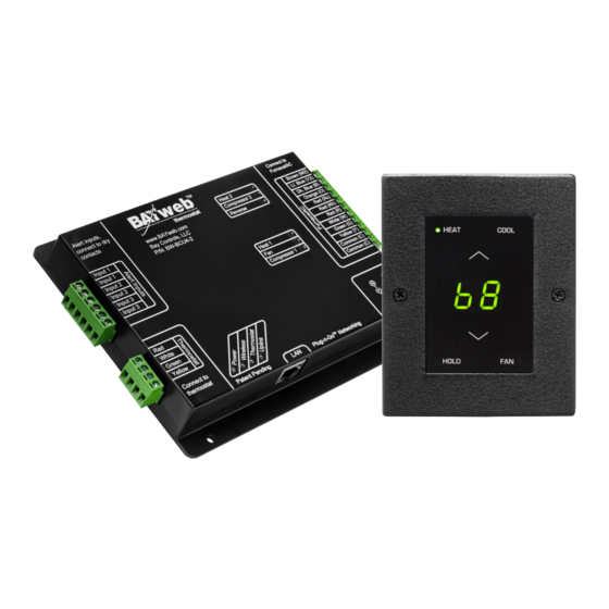
Reference Thermostat Keypad The Thermostat Keypad module senses the current temperature and provides an interface for manual control. Normally the displayed number (68 in this case) indicates the current temperature. To change the set point, press the up or down arrows. The display will switch to the current set point. -
Page 23: Control Module
Indicates that the temperature sensor in the keypad module has failed. Indicates that DHCP (Dynamic Host Configuration Protocol) is not functioning on your local network. Indicates that the control module has lost communication with the BAYweb servers. Indicates that the non-volatile memory was corrupted or lost. Control Module... -
Page 24: Thermostat Connector
Power Supply The power supply connector is used to power the BAYweb Thermostat if your furnace/AC does not provide the common power wire (“C” or “X” terminal). See installation Step 1D. Ideally the power supply should be plugged into the same circuit that powers the furnace/AC. -
Page 25: Troubleshooting
Thermostat Keypad module. Uplink Indicates that the control module is successfully communicating with the BAYweb servers. Troubleshooting We encourage you to communicate any problems you have encountered to us, even if you are able to solve them on your own. We would also like to have any suggestions or comments about the installation procedure. -
Page 26: Solutions To Problems
We suggest you review the Solutions to Problems section and check the support resources www.bayweb.com which may provide you with a simple solution to the problem. Solutions to Problems Problem Solution No Control Module power indication. ✔ Check for 24VAC power between terminals “R”... - Page 27 Problem Solution Heat does not function. ✔ Verify that Heat mode is selected on the Thermostat Keypad. ✔ Verify that the set point is higher than the current temperature. ✔ Verify on the Control Module that the Heat light is ON. ✔...
- Page 28 Problem Solution Thermostat Keypad shows error code “E1”: ✔ Check the wiring and connections between the Thermostat Keypad and The Thermostat Keypad is not communicating Control module. Make sure all 4 wires with the Control Module. are connected. ✔ Try wiring the Thermostat Keypad directly to the Thermostat connector of the Control module.
- Page 29 Problem Solution Wireless occupancy sensor not working. ✔ Verify the X10 ID settings – see the settings page. ✔ Verify the X10 ID settings of the sensor, refer to the instructions provided with the sensor. ✔ Check that the Wireless light on the Control Module turns ON when the sensor is activated.
-
Page 30: Obtaining Support
Eastern time. Support requests received after midnight are handled the following morning. Optional Inputs The BAYweb Thermostat has three input channels that can be used for a variety purposes. This section describes the optional monitoring and control functions that are available. To enable and configure the option, refer to the “Inputs”... -
Page 31: Outdoor Air Temp
Outdoor Air Temp Typically the BAYweb Thermostat obtains the outdoor air temperature from a local weather station using the network connection. An optional outdoor temperature probe can be used for locations that do not have a local weather station that provides a representative outdoor temperature. -
Page 32: Thermostat Connections
configured as a damper control signal for zoned systems. The damper control is active whenever the system is heating, cooling, or when the fan is on. Thermostat Connections The following table shows all standard thermostat terminals and associated functions. Terminal Function Standard Wire Color 24 VAC Supply (heat &... -
Page 33: Specifications
Specifications Part Numbers: BW-WT8 (specify color) Thermostat Keypad: BW-T100 or BW-T110 (specify color) Control Module: BW-BCU4-8 Control Types: Single and multistage heat/cool, heat pump with aux heat Fan Control: Auto, On, auto with minimum circulation Set Points: 4 heat, 4 cool...
Need help?
Do you have a question about the BW-WT8 and is the answer not in the manual?
Questions and answers