Advertisement
Advertisement
Table of Contents

Related Manuals for Acson ACK15BW


Summary of Contents for Acson ACK15BW
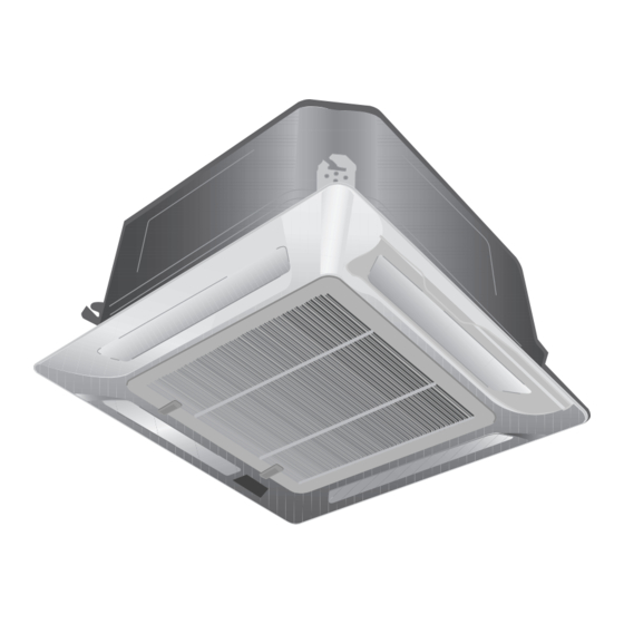
- Page 1 CEILING CASSETTE CHILLED WATER FAN COIL UNIT (B & C SERIES) INSTALLATION MANUAL IM-CKBCW-0503(0)
-
Page 3: Outline And Dimensions
OUTLINE AND DIMENSIONS Indoor Unit : CK15BW / 20BW / 25BW / 30BW All dimensions are in mm. Indoor Unit : CK10CW / 15CW / 20CW All dimensions are in mm. - Page 4 ! Caution Sharp edges and coil surfaces are potential locations which may cause injury hazards. Avoid from being in contact with these places. ! Avertissement Les bords coupants et les surfaces du refroidisseur tubulaire présentent un risque de blessure. Mieux vaut éviter le contact avec ces endroits. ! Vorsicht Scharfe Kanten und Wärmetauscherflächen stellen eine Gefahrenquelle dar.
- Page 5 Before using your air conditioner, please read this instruction manual carefully and keep it for future reference. CEILING CASSETTE CHILLED WATER FAN COIL UNIT MODEL Reference Model Model CK15BW ACK15BW / MCK015BW / YCK15BW CK20BW ACK20BW / MCK020BW / YCK20BW CK25BW ACK25BW / MCK025BW / YCK25BW CK30BW...
-
Page 6: Table Of Contents
CONTENTS - Indicator Lights page 9 - Outline And Dimensions page i – ii - Overall Checking page 9 - Safety Precautions page 2 - Auto Random Re-Start Function page 9 - Installation Diagram page 3 - Service and Maintenance page 10 - Installation of Indoor Unit page 3... -
Page 7: Installation Diagram
INSTALLATION DIAGRAM Drain Hose Indoor Unit IR Receiver LED Light Front Panel Air Filter (behind the grille) Air Discharge Louver Wireless Remote Control Wired Remote Control Air Intake Grille Water Piping Air Intake Netware - 2 Air Intake SLM - 3 Air Discharge Nozzle Outdoor Unit INSTALLATION OF INDOOR UNIT... - Page 8 Unit Installation • Measure and mark the position for the hanging rod. Drill the hole for the angle nut on the ceiling and fix the hanging rod. • The installation template is extended according to temperature & humidity. Check on dimensions in use. •...
- Page 9 Drain Test • Connect the main drain pipe to the flexible drain hose. • Feed water from flexible drain hose to check the piping Feed Water for leakage. Main Drain Pipe • When the test is completed, connect the flexible drain hose to the drain connector on the indoor unit.
-
Page 10: Electrical Wiring Connection
ELECTRICAL WIRING CONNECTION This is a proposed wiring connection. It may change subject to the chiller unit and must comply with the local and national code and regulations. MODEL : CK15BW - CK30BW FCU 1 FCU 2 FCU 3 COMP L/L1 N/L2 N/L2 COMP L/L1 N/L2 N/L2... - Page 11 MODEL : CK15BW / 20BW / 25BW / 30BW...
- Page 12 MODEL : CK10CW / 15CW / 20CW...
-
Page 13: Indicator Lights
Wire termination to the controller board is as shown in the wiring diagrams. The standard controller board (W1V3) comes with a VALVE (JVLV) jumper and a HEAT (OD) jumper. The system must be configured as the jumper selection listed below: HEAT Jumper VALVE Jumper ×... -
Page 14: Service And Maintenance
! Caution Before turning off the power supply, set the remote controller's ON/OFF switch to the “OFF” position to prevent the nuisance tripping of the unit. If this is not done, the unit's fans will start turning automatically when power resumes, posing a hazard to service personnel or the user. - Page 16 • In the event that there is any conflict in the interpretation of this manual and any translation of the same in any language, the English version of this manual shall prevail. • The manufacturer reserves the right to revise any of the specification and design contain herein at any time without prior notification.
Need help?
Do you have a question about the ACK15BW and is the answer not in the manual?
Questions and answers