Table of Contents
Advertisement
Quick Links
Download this manual
See also:
User Manual
Advertisement
Table of Contents

Related Manuals for Team Nisca PR5300


Summary of Contents for Team Nisca PR5300
- Page 1 DIRECT CARD PRINTER PR5300 Operation Manual Ver. 1.3 Aug.'00...
-
Page 2: Table Of Contents
Contents Section 1 For your safety a) Before installing b) Before turning power ON c) Before using d) Before moving the equipment e) About laws and regulations F) Prohibited matters Section 2 Preparation a) Package csntents b) Consumables c) Parts tobereplacedperiodically d) Name of theparts Section 3 : Installation... - Page 3 Section 1: For your safety Several illustrations are used in this operation manual to ensure safe operation. The following conventions are used to identify the result caused by the use or operations not following such illustrations. :This indicates that there is a danger of death or serious injury.
-
Page 4: Before Installing
1- Before installing About environment for installation Do not install in humid and dusty room.It may cause fire and/or electric shock. Do not install the equipments near the heat emitting apparatus such as stove and heater or near the flammables such as curtain. - Page 5 Do not place where there is direct sunlight. It may cause deformation ofplastic housing and decoloration of the prints. 15cm 6inch Enough space must be provided around the equipments. This is necessary for easy operation as well as for ventilation. 15cm 15cm 6inch...
- Page 6 1- Before turning the power ON About power source Do not use any other outlet than followig. Do not connect more than one equipments onto one outlet. Otherwise, it may cause a fire and/or electric shock.The specified rating of this equipment is following. 100 ‘240 VAC Dust on the plug and electrical outlet mustbe removed.If used without removing, a small amount of electricity runs continuously through the dust...
- Page 7 About connecting the grounding line Grounding line must be connected. If the equipment is not grounded and there is an electric leakage, it may cause electric shock or fire. qGrounding line may be connected to the following points. r Grounding terminal on the electric outlet The line connected to an copper rod which is buried in the ground at the depth of 65cm(26inch) or deeper.
- Page 8 1- Before using About handling the equipment Do not put anything containing water such as vase etc. on the equipment. If water is spilled, it may cause fire or electric shock. Do not put any metal pieces such as paper clips on the equipment.
- Page 9 If smoke or unusual smell is detected, stop using. If it is used as it is,it may cause fire or electric shock. Turn OFF the main switch immediately,plug off the power cord and contact the dealer from whom the equipment was purchased. In case of thunder, for the purpose of safety, turn OFF the main switch and plug off the power cord.
- Page 10 About handling of the equipment Do not put any heavy article on the equipment. It may damage the equipment or cause the injury by dropping. Do not use flammable sprays at near the equipment. It may catch fire and cause fire accident. When the front door is open, do not put anything on the door or lean on.
-
Page 11: D) Before Moving The Equipment
1- Before moving the equipment About power source Turn OFF the main switch and plug off the power supply cord from the outlet before moving the equipment. Otherwise, it may damage the power cord and cause a fire. To pull off the plug of the power cord, hold the body of the plug and pull off. -
Page 12: Preparation
Section 2: Preparation - a) Package contents Following items are packed in the carton together with the printer. If anything is missing, contact the dealer from whom you have purchased. Power Supply Cord Empty Bobbin Stacker Box Weight Operation Manual (You are reading) 2 x Ferrite Cores (Bandled with only for the equipment with... - Page 13 - b) Consumables Ink ribbons and cards must be prepared to use this printer. Ink Ribbons The following 2 kinds of ribbons are used for this printer. Name Marking Number of frames Reference (Per roll) Dye sublimation type full color PR5002 3KO ID-3BP + heat meltingblack+Overcoat...
-
Page 14: C) Parts Tobereplacedperiodically
- c)Parts to bereplaced periodically Spare Print Head and Input Rollers are available for periodic replacement in order to ensure the optimum print quality and long life of machine. PrintHead The Print Head comes whith the floppy disk which contains the data for best print quality assured. - Page 15 Input Roller Periodic replacement cycle for the Input Roller is every 40,000 frames if the recommended cards are used and cleaning is done every 2,000 frames. To exchange the Roller, refer the item "Replacing Input Roller"at 7-a) For cleaning the Rollers, refer the item "Cleaning the rollers"at 6-a) - 13 -...
-
Page 16: D) Nameoftheparts
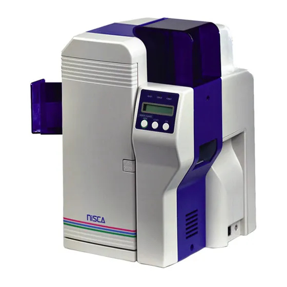
- d) Nameoftheparts Front side of the printer @Front Access Cover ATop Cover BRear Cover COperation Panel DCard Feeding Unit EPower Switch FReject Card Exit GFront Cover HCard Stacker - 14 -... - Page 17 Rear side of the printer A) SCSI type interface equipment Circuit Protecter ASCSI Connector BOptional Unit Connector CPower Cord Receptacle DTerminate Switch - 15 -...
- Page 18 Rear side of the printer B) PARALLEL type interface equipment Circuit Protecter PARALLEL Connector BOptional Unit Connector CPower Cord Receptacle - 16 -...
-
Page 19: Front Access Panel
Front Access Panel @Input Roller Module ARibbon Cartridge Holding Lever BManual Rotation Knob CRibbon Cartridge - 17 -... -
Page 20: Installation
Section 3: Installation First, please confirm that you have read the Cautions about installation. - a) Environment forinstallation The equipment can be used in the ambient temperature of 10 `35 KC i50 `95 but to ensure the best performance, temparature range of 20 `25 KC i68 `77 is recommended. -
Page 21: D) Connecting The Printer To Computer
- d) Connecting the Printer to Computer - d-1) For SCSI type interface When constructing a system with the plural number of devices, connect the SCSI compatible terminal devices ( SCSI devices) including this printer in the chain connection as shown in the following fig. Those SCSI devices designed to suit for such connection has two SCSI connectors For example,one is us ed for interfacecable... - Page 22 Setting the Terminating Switch Depending on the system structure, this printer may be connected at the end or middle of the SCSI chain (daisy chain) . Turn ON or OFF the terminating switch accordingly as shown in the following figs. In case of the printer is in the middle: TER MINATOR Terminating Switch should be"...
- Page 23 Connecting Cable Please follow the instruction of the system for the selection of the cable. The interface of this printer is SCSI specification. The printer side connector is [Pin type Half 50 pin male]. The other end shall meet the type of the connector of the computer or SCSI devices to be connected.
- Page 24 - d-2) For Parallel type interface Connecting Cable The printer side connector is [Amphenol Half pich 36 pin male]. The other end shall meet the type of the connector of the computer. Connect the[Amphenol Half pich 36 pin male] type side to the back of Printer at the connector with displaied as "PARALLEL"...
- Page 25 Power ON The electrical rating of power for this printer is alternate power (AC100V }10%,50 Hz or 60Hz). Earth must be securely connected for this printer. The maximum power consumption of this printer is 120W. Avoid power failur or voltage drop as much as possible. When the power is turned OFF, wait for at least 3 sec.
-
Page 26: Operation Panel
Section 4 Operation Panel Outline of the OperationPanel Appearanceandcomposition ERROR READY POWER RIBBON CHANGE MENU CLEAR CLEAR MENE Function of each parts The functions of LCD and the three keys (Menu, Clear, Exe) are different for Normal Mode ( after the power is turned ON and before entering the User Mode) and for the User Mode. -
Page 27: B) Operation Of Normal Mode
Operation of Normal Mode When the power is turned ON, the printer is in Normal Mode. Power LED (Green) turns ON and the printer status is shown on the panel. Normal Mode is the mode for printing, and the printer status is shown on the "Ready to Print"... - Page 28 EXE key print This is the function to repeat printing the data stored in the printer memory b pressing the key. However, to effect this function, it is necessary to set EXE Key Print to ON position in the user mode. This function is invalid regardless of the setting in the user mode if the system is designed so that th data is not stored in the printer memory to prevent double printing.
- Page 29 Operation ofthe User Mode User Mode is used to set the printer setting for the user environment or to check the printer status. Switching to User Mode MENU 1.Press and hold the key on the READY ERR OR P OWER Operation Panel as illustrated.
-
Page 30: D) Function Of User Mode
Functions of User Mode Checking thenumberof cards used: CardCount Indicates the number of the cards taken-in from the card feeder. It returns to Clear by pressing key. ¤ To be used for the control of card consumption. Total count of the printed frames: TotalCount This is a maintenance counter for the accumulated number of the frames printed. - Page 31 ON/OFF of theerror buzzer: Error Buzzer Select ON/OFF of the error alarm buzzer which sounds when the errors such as "Cover Open" "Card Empty" occur. Ribbon type setting: Ribbon Type "YMCK01" "K01" for color printing and for black letters are used as the standard ribbons for this printer.
- Page 32 Setting the System Environment: Printer Status This item must be set according to the system being used. So, follow the system instructions for setting. To enter this menu, in order to prevent operational error, follow the instruction on the display and press Clear key and Exe key at the same time. Others are same as the basic operation.
- Page 33 e) Structure of Uer Mode Theitems shown with are to b e s e t b y t h e Ready to Print User. Default settings isshownbythewhiteletters Removable Ribbon ontheblackbackground User Mode Thedisplay surrounded with appearsonly CLR:BACK EXE:GO when thecorresponding optional unit is connected User Mode Sub-menus as shown with re listed in thenextpage.
- Page 34 Ribbon Type Ribbon Type EXE:sub menu Push MENU key YMCKO1 Ribbon type will be Printer Ribbon changed when EXE key pressed. HARD COAT TYPE1 H.Roller Ribbon « HARD COAT TYPE2 ************ « SOFT COAT TYPE1 « Return to SOFT COAT TYPE2 «...
-
Page 35: A) Setting Cards
Section 5: How to Set Cards and Ribbon - a ) Setting cards Do not use the card other than designated by the dealer. ¤ Otherwise, it may not produce the normal print quality and cause trouble on the equipment. Double printing on the card which has been printed with this printer is not possible. - Page 36 When loading the cards, stack the cards evenly as marked with in the figure below. If it is stacked unevenly as shown with the mark in the figure below, it may casue "Pick Up Error" or the stack may collapse. - 34 -...
-
Page 37: B) Setting The Ink Ribbon
- b) Setting the ink ribbon When taking out the ink ribbon cartridge before it becomes empty "Ribbon Empty" (while LCD panel displays other than ), press RIBBON CHANGE key and confirm that the head is lifted. ¤ Cartridge can not be removed with the head at the printing position. The ribbon may be wrinkled or broken if the cartridge is removed forcibly. - Page 38 Release the lock of Ribbon Cartridge and open as illustrated. Peel off the remaining ribbon from the supply bobbin. Dispose of the take up bobbin with the full used ribbon. Place the now empty supply bobbin in the take up side of the cartridge to use as take up bobbin.
-
Page 39: Cleaning
Section 6 F Cleaning To ensure the optimum print quality, precision components and electornic parts are used for this printer. Stain on rollers and print head is crucial to the print quality. To maintain the best print conditons, observe the following poi Clean these parts periodically to keep the optimum performance. -
Page 40: A) Input Roller
- a) Input Roller Before starting this operation, please read the general advice which appears in the beginning part of this section. Remove the Input Roller module as explainedin Page 00 and clean in the following procedure. Wet and squeeze a piece of soft cloth with alcohol for cleaning OA equipment and wipe in the direction as illustrated. -
Page 41: C ) Cleaningoftheprintrollers
- c ) CleaningofthePrintRollers This Operation shall be done by a service personnel. Before starting this operation, please read the general advice which appears i the beginning part of this section. Turn OFF the power without fail before the cleaning operation. ¤It may cause a trouble and/or to have electrical shock. -
Page 42: E) Cleaning Of The Suply Roller
- e) Cleaning of the Supply Roller Before starting this operation,please read the general advicewhich appears in the beginning part of this section. Wet and squeeze the soft cloth with alcohol for OA equipments and wipe the all surface of the roller in the direction as shown by arrow in the figure below. -
Page 43: F) Cleaningoftheprinthead
- f) CleaningofthePrintHead The Print Head will be remaining hot when just after Printing. Before starting this operation, make sure that the Print Head module has been cool. Turn OFF the power without fail before the cleaning operation. ¤It may cause a trouble and/or to have electrical shock. Do not use solvents other than alcohol for cleaning OA equipments ¤Using the solvent other than alcohol may damage the parts and may cause... -
Page 44: Periodical Replacement Ofparts
Section 7: Periodical replacement of parts This printer offers a superb performance for long period with very high reliability. But to maintain the performance, some parts need to be replaced periodically. This means the low running cost. Replacement can be easily done if the operator has basic knowledge or experienc of handling electronic machinery. -
Page 45: B) Replacing Printhead
- b) Replacing PrintHead The print head comes with a floppy disk which contains the data for assuring best print quality. The data in floppy disk must be loaded to the printer when the print head replaced. Turn OFF the main switch and pull out the plug of power cord before the replacement operation in order to prevent the danger of electric shock and possible cause of equipment trouble. - Page 46 - 44 -...
-
Page 47: Basic Specification
Section 8: Basic Specification 1 Printing Method Image Area : Dye Diffusion Thermal Transfer CharacterArea : Molten Type Thermal Transfer Protective Layer : Molten Type Thermal Transfer system 2 Printing Media PVC Card Comforms to ISO7810,JISX6301 or madeofothermaterials with receivable layer on the surface Sise : 54.5mmx85.5mm Thickness : 0.76 + - 1 0 % m m 3 Printing Resolution... -
Page 48: Configuration Ofthe Equipment
Section 9: Configulation of the equipment Card Supply Unit PicksupacardfromthebottomofthestackandfeedstotheprinterwiththeSupplyRoller. The slotis 1.5 times of the thickness of thecard so that the double feeding will notoccur. Cleaning Unit Remove theimpediments such as dusts on the surface of the card fed from FeederUnit Flip Turn Unit This unit serves to flipoverthecardandtoswitchthecardpathtoprintingunit, reject unit or to encodeunit. - Page 49 Section 10: Trouble and Countermeasure 1 0 - Troubles displayed on theoperationpanel If a trouble occurs, the red lampontheoperation panel turnsONandthenatureofthetroubleis shown on the LCDpanel. In addition to the indication of ribbon empty and card empty,almost all kinds of troubles such assettingof the ribbon type, position of card jam,etc.,can becheckedwiththe messages on the LCDpanel Display of trouble o n the LCD panel If messages which is notlisted below appearsorthetroubleisnotreleased, pleasecontact the dealer.
- Page 50 Trouble shooting Message on LCD Cause/Countermeasure Ref. Card Empty Card isempty. P 34 Supply cards. ¤ Card is empty Front Cover is Front Cover isnotclosedcorrectly. Open Closethecoverpositively. ¤ FrontAccesscover is open Top Cover is Top Coveris not closed correctly. Open Closethecoverpositively.
- Page 51 Message on LCD Cause/Countermeasure Ref. PleaseCheckInk This messageisshownwhentheClearkeyispressedwithout P.47 Ribbon taking outtheribboncartridgewhentheinkribbonrelatederrors Pull outthecartridgeandchecktheribbon,thenreleasetheerror ¤ and presstheClearkey. Ribbon Empty The inkribbonisfinished P.35 Replacewiththefreshinkribbon. ¤ Ribbon Type The ribbon type settingoftheprinterandtheribbontype actually Incorrect beinguseddonotcorrespond. Pull outtheribboncartridgeafterpressingthe ¤ MENU/ Ribbon Change k e y a n d c h e c k t h e t y p e o f t h e r i b b o n i n the cartridge.
- Page 52 Releasing card jam Most of the card jamerrorsarecausedbydirtand stain of the card transport rollers. If the rollersaredirty,cardjamerrorfrequentlyoccur.To prevent this, periodic rollercleaning as described in paragraph 6 is recommended. Dependingontheposition of thecardjam, you may have toputyourhandintheprinter. Please be careful when doing so and be sure to turn OFF the powerbefore beginning the work. Usually, jammed card can be ejected automatically to the Card Eject Exit bypressingClear key on the operation panel.
- Page 53 Block Layout...
- Page 54 Card Jam which can not bereleased b y Clear key Message o n L C D Cause/Contermeasure Q ˘ Card JAM Feeder Card isnottakenintothe printerandremaininginthe Area Feeder Block. RemoveallcardsintheFeederandsetthemagainafterseparating ¤ theedges of the cards. After setting, press Clear key torecoverthe error.
- Page 55 Trouble which is not displayed on the operation panel Problem Cause/Countermeasure Ref. Color drop Ifadustisonthesurfaceofthecardwhenprinting, Partial drop or discoloration thepartofthedustremainsunprinted Thedustmaydisappearafterprinting. D o n o t u s e t h e c a r d h a v i n g a d u s t o n t h e f a c e . ¤...
- Page 56 Problem Cause/Countermeasure Ref. Thecoloroftheprintedimagesuddenly Iftheribboncartridgeis takenoutwithoutpressing changes in themiddle. Ribbon Changekeyandre-set again, the firstframe isprintedandoutputwiththistrouble. When takingouttheribboncartridge with remaining ¤ ribbon,donotforget topressRibbonChange key beforetakingout. Themessage"RibbonTypeincorrect"isshownon the L C D display. This doesnotmeanthe machine troublebutmeansincorrectoperation. UnsupposedDarkarea appeares on the Thisproblem iscausedbyamaterialofthecard. Printed image.
- Page 57 Other troubles Problem Cause/Countermeasure Ref. PowerdoesnotturnON. Check theconnectionofthepowercord. Ifthecircuitprotectorleverabovethe power cord P.15 receptacleonthebacksideoftheprinteris protruding. Please callyourdealer. ¤ ForSCSI type Interface Equipment Data cannotbetransmittedto P.19 theprinter. Check thattheSCSIIDnumberisnotconflicting withotherdevice s . P.19 Turn O F F t h e p o w e r o f t h e s y s t e m a n d t u r n O N again.Please be surethat theprinterandtheother devicesstartbefore thecomputer.
Need help?
Do you have a question about the PR5300 and is the answer not in the manual?
Questions and answers