Summary of Contents for Nokia HSU–1
- Page 1 After Sales Technical Documentation Handset HSU–1 NMP Part No. 0275276 Original 50/96...
-
Page 2: Table Of Contents
After Sales Handset HSU–1 Technical Documentation CONTENTS Handset HSU–1 ........–... -
Page 3: Handset Hsu-1
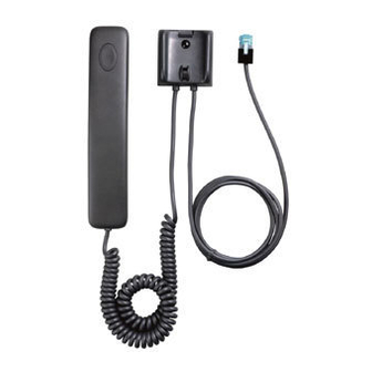
After Sales Handset HSU–1 Technical Documentation Handset HSU–1 Introduction Main function of the HSU–1 Audio Handset is to form an electroacoustic interface between the user and the phone environment. Technical Summary The HSU–1 Audio Handset consists of handset with coil cord and of cradle. -
Page 4: Technical Specifications
After Sales Handset HSU–1 Technical Documentation Technical Specifications Modes of Operation DG–1 module has only one mode of operation. Audio paths will become active when the handset is lifted from the cradle. Otherwise muting is on. Maximum Ratings –supply voltage: 16.0 V –operation temperature range, specification: –... -
Page 5: External Signals And Connections
After Sales Handset HSU–1 Technical Documentation External Signals and Connections The HSU–1 Audio Handset has an 8 pin modular connector at the end of the coil cord to the junction box. There are only five lines in use in the coil cord. -
Page 6: Earphone Amplifier
After Sales Handset HSU–1 Technical Documentation – HOOK switch ( REED relay ) – Voltage regulator Earphone and microphone paths are controlled by Hook switch, which is opened automatically, when the handset is lifted from the cradle. In the cradle there is a magnet and in the handset there is a reed relay. Reed relay controls audio switches. -
Page 7: Voltage Regulator
After Sales Handset HSU–1 Technical Documentation Voltage Regulator Supply voltage to DG–1 module is fed via connector X1 pin 1. Voltage is regulated with regulator N1 ( LP2951 ACM ). Capacitors C4 and C1 are used to improve filtering. Bias voltage for Mic and Ear signals and amplifi- ers is made byamplifier N2C (TL074ID). -
Page 8: Circuit Diagram Version 6.0
After Sales Handset HSU–1 Technical Documentation Circuit Diagram version 6.0 Original 50/96 Page – 8... -
Page 9: Layout Diagrams
After Sales Handset HSU–1 Technical Documentation Layout Diagrams Page – 9 Original 50/96... -
Page 10: Parts List Of Dg1 (Version 1.1) Code 0200221
After Sales Handset HSU–1 Technical Documentation Parts List of DG1 (Version 1.1) Code 0200221 ITEM CODE DESCRIPTION VALUE TYPE R001 1414036 Chip resistor 8.2 k 5 % 0.1 W 0805 R002 1412430 Chip resistor 10 k 5 % 0.1 W 0805 R003 1413635 Chip resistor 100 k... - Page 11 After Sales Handset HSU–1 Technical Documentation C015 2310544 Ceramic cap. 1.0 n 5 % 50 V 0805 C016 2310336 Ceramic cap. 18 p 5 % 50 V 0805 C017 2604431 Tantalum cap. 10 u 20 % 16 V 6.0x3.2x2.5 C018 2604209 Tantalum cap.
-
Page 12: Exploded View
After Sales Handset HSU–1 Technical Documentation Exploded view Assembly parts ITEM Q’TY CODE DESCRIPTION VALUE, TYPE 9450302 Front cover 2D 23151 HSU–1 9459393 Bottom cover 2D 23152 HSU–1 9450132 Mic spacer 4D 21588 NHE–2 9450133 Earphone spacer 4D 21596 NHE–2 9450304 Cradle cover 2D 23153 HSU–1... - Page 13 After Sales Handset HSU–1 Technical Documentation 5140379 Cond. microphone 62 3 dB 2.2 kΩ 6x5 5140578 Receiver capsule 103 2 dB 9510193 Earpiece clip 4D 24147 6291917 PT screw KB25x5 FeZn clr 0200221 Handset module DG–1 Page – 13 Original 50/96...
- Page 14 After Sales Handset HSU–1 Technical Documentation [This page intentionally left blank] Original 50/96 Page – 14...


Need help?
Do you have a question about the HSU–1 and is the answer not in the manual?
Questions and answers