
Related Manuals for VocoPro STAGE-MAN

Summary of Contents for VocoPro STAGE-MAN
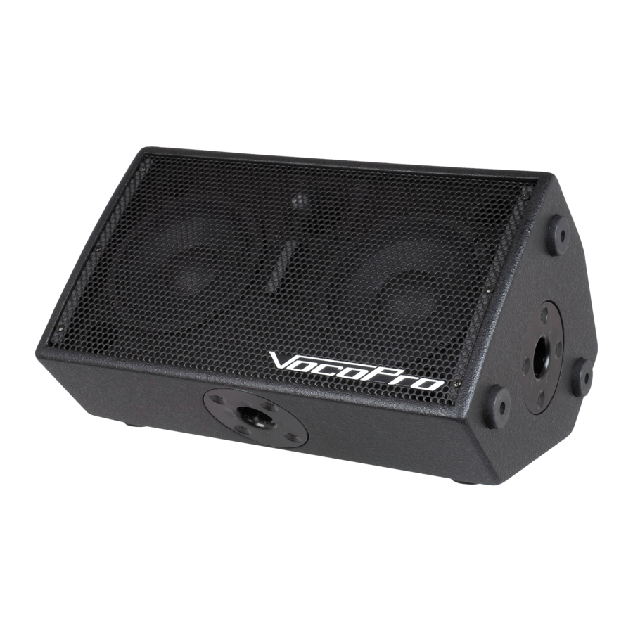
- Page 1 STAGE-MAN 200W 3-Channel Active Vocal Monitor with DSP Effects...
-
Page 3: Table Of Contents
Table of Contents Safety Instructions . . . . . . . . . . . . . . 4 FCC Information . . . . . . . . . . . . . . . . 5 Welcome . -
Page 4: Safety Instructions
Safety Instructions 8. Ventilation - The appliance should be situated so its location does not interfere with its proper ventilation. CAUTION For example, the appliance should not be situated on a bed, sofa, rug, or similar surface that may block the RISK OF SHOCK ventilation slots. -
Page 5: Fcc Information
1. To ensure the finest performance, please read this requirements. Modifications not expressly approved by manual carefully. Keep it in a safe place for future Vocopro may void your authority, granted by the FCC, reference. to use this product. 2. Install your unit in a cool, dry, clean place - away from 2. -
Page 6: Welcome
And while you're there don't forget to check out our Club VocoPro for Karaoke news and events, chat rooms, club directories and even a KJ Service directory! We look forward to hearing you sound like a PRO, with VocoPro, the singer’s ultimate choice. FOR YOUR RECORDS Please record the model number and serial number below, for easy reference, in case of loss or theft. -
Page 7: Listening For A Lifetime
Now itʼs time to consider how you can maximize the fun and excitement your equipment offers. VocoPro and the Electronic Industries Associationʼs Consumer Electronics Group want you to get the most out of your equipment by playing it at a safe level. One that lets the sound come through loud and clear without annoying blaring or distortion and, most importantly, without affecting your sensitive hearing. -
Page 8: Features
• Individual loop jacks on each channel for connecting to external effects devices • Five-band equalizer to fine-tune the sound of your source music • Retain full control over your vocal sound on stage without the need of a soundman • Wireless modules available to expand your STAGE-MAN... -
Page 9: Before Getting Started
Before Getting Started Thank you for purchasing the STAGE-MAN system. The STAGE-MAN will provide years of reliability and high qual- ity entertainment for you if used properly. Please read this manual carefully before using your STAGE-MAN to ensure best performance . -
Page 10: Getting Connected
Getting Connected CH 1-2 Connections The ¼” – XLR combo jacks on CH 1 and CH 2 allow you to connect up to two wired dynamic microphones or musical instruments. Note that UHF modules are installed on either CH 1 or CH 2, they will share the channel with devices connected to the ¼”... - Page 11 (may be labeled TIP) to an input jack, and connect the “return” ¼” plug (may be labeled RING) to an output jack. NOTE: Please refer to the instruction manual of your external effects device for more information on connecting it to the STAGE-MAN CH 1...
-
Page 12: Getting Connected
Getting Connected Balanced Input and Output Use these jacks to link multiple STAGEMANs together for extra power. When multiple STAGEMANs are con- nected, the first in the chain is the master unit. The units after that are slave units that only act as powered speakers. -
Page 13: Descriptions And Features
2. CH 1 EXPANSION port – Use this port to install a UHF wireless module to CH 1. NOTE: CH 1 UHF module is included with STAGE-MAN-I and STAGE-MAN-II models. If you purchased a STAGE-MAN (basic), UHF modules can be purchased separately.) 3. - Page 14 Descriptions and Features CH 1 CH 2 OPTIONAL ACCESSORY EQUALIZER Effect Level Echo Delay Echo Level Echo Repeat Reverb Level LCF Control EFFECTS +63Hz TOGGLE FOOT SWITCH CH 1 MAIN DIGITAL SD RECORDER 250Hz CH 2 SDR-3 SDR-3 OPTIONAL ACCESSORY PLAYBACK POWER ROUTE...
- Page 15 Descriptions and Features CH 1 CH 2 OPTIONAL ACCESSORY EQUALIZER Effect Level Echo Delay Echo Level Echo Repeat Reverb Level LCF Control EFFECTS +63Hz TOGGLE FOOT SWITCH CH 1 MAIN DIGITAL SD RECORDER 250Hz CH 2 SDR-3 SDR-3 OPTIONAL ACCESSORY PLAYBACK POWER ROUTE...
- Page 16 Descriptions and Features Rear Panel 1. POWER terminal – Connect power cable to this terminal. 2. POWER ON/OFF switch – Use this switch to turn the unit OFF/ON. 3. HEADPHONE jack (1/4”) – Connect a set of headphones with a ¼” plug to this jack. NOTE: Connecting headphones mutes the main amplifier output.
-
Page 17: Operations
7. PLAY LED – This orange LED will illuminate during playback of recorded material, and during a recording in progress. 8. POWER LED – This green LED indicates the SDR-3 is on and drawing power from the STAGE-MAN. This LED should il- luminate and stay lit as long as the STAGE-MAN is powered on. - Page 18 Operations 10. REC LEVEL LEDs – These LEDs visually represent the gain level of the signal being recorded. There are five green LEDs and two red LEDs. An optimal recording level will illuminate all the green LEDs with minimal activity on the red LEDs. 11.
- Page 19 UHF Wireless Channels (STAGE-MAN-II Only) There are two UHF wireless microphone modules (sold separately) available with the STAGE-MAN. Use the CH 1 & 2, and DSP controls to make adjustments to UHF microphone signals. Refer to the information below to setup and use your UHF wireless microphone(s).
- Page 20 2. Insert 2 fresh 1.5-volt AA alkaline batteries. Make sure the batteries are inserted in the right direction according to polarity (+/-) Basic Operations 1. Press the POWER switch on the front panel of the STAGE-MAN. 2. Adjust the module level controls to approximately 50%. 3. Switch the microphone’s power switch to the ON position.
-
Page 21: Technical Specifications
Technical Specifications STAGE-MAN SPECIFICATIONS Mixer Input Specification (At Main L/R Output, +4dBu, 1kHz) INPUT CONNECTION LEVEL (RATED IN- TOTAL GAIN IMPEDANCE PUT) Mic INPUT (CH1-CH2) XLR (BAL) -50dBu 54dB 1Kohm Mic INPUT (CH1-CH2) 1/4” TRS (BAL/UN- -50dBu 54dB 1Kohm BAL) - Page 22 Technical Specifications 5 Band Graphic EQ 63Hz ±12dB 250Hz ±12dB MAIN MIX OUTPUT (XLR/BAL) 1KHz ±12dB 3.5KHz ±12dB 12KHz ±12dB T.H.D+N BAND PASS ON (20 Hz to 20KHz BANDWIDTH) OUTPUT LEVEL T.H.D MIC MONO to Speaker Output @ Unity 1/2 Power Less than 0.09% Gain Input CH3 to Speaker Output @ 0dBu Gain...
-
Page 23: Technical Specifications
Technical Specifications Maximum Input Level INPUT CONNECTION LEVEL XLR(BAL) -22dBu MIC INPUT 1/4” TRS (BAL/UNBAL) -22dBu CD RCA Stereo (UNBAL) +5dBu MUSIC INPUT CH3 MP3 1/8” PHONE (UNBAL) TIP: +4dBu LEFT, RING: RIGHT Effect Controls (D.S.P) Reverb/Delay Control Echo Delay 40mS-242mS Echo Repeat 30%-80%... -
Page 24: Troubleshooting
. This is called interference. Remove local sources of UHF interference, such as lighting equipment. In some locations this may be unavoidable due to a frequency conflict. Contact VocoPro tech support for more information. Momentary loss of sound as microphone(s) are moved throughout the operating range. - Page 25 Troubleshooting Recordings are distorted . Lower the recording level on the SDR-3 . If routing SDR-3 playback to EQ, check the EQ settings, and readjust in necessary .
-
Page 26: Notes
Notes... - Page 27 Notes...
- Page 28 STAGE-MAN Owner’s Manual © VocoPro 2012 v1.1023 www.vocopro.com...
Need help?
Do you have a question about the STAGE-MAN and is the answer not in the manual?
Questions and answers