LG LAN091CNP, LAU091CNP, LAN121CNP Service Manual
Lg room air conditioner service manual
Hide thumbs
Also See for LAN091CNP, LAU091CNP, LAN121CNP:
- Service manual (77 pages) ,
- Manual (76 pages) ,
- Owner's manual (31 pages)
Table of Contents
Advertisement
Quick Links
LG
Room Air Conditioner
SERVICE MANUAL
MODELS: LAN091CNP (ASNC091F2G0)
LAU091CNP (ASUC091FUG0)
LAN121CNP (ASNC121F2G0)
LAU121CNP (ASUC121FUG0)
LAN091HNP (ASNH091F2G0)
LAU091HNP (ASUH091FUG0)
LAN121HNP (ASNH121F2G0)
LAU121HNP (ASUH121FUG0)
LA090CPI (ASNC091F2G0)
LA090CPO (ASUC091FUG0)
LA120CPI (ASNC091F2G0)
LA120CPO (ASUC091FUG0)
LA090HPI (ASNH091F2G0)
LA090HPO (ASUH091FUG0)
LA120HPI (ASNH121F2G0)
LA120HPO (ASUH121FUG0)
website http://www.lgservice.com
CAUTION
• BEFORE SERVICING THE UNIT, READ THE SAFETY
PRECAUTIONS IN THIS MANUAL.
• ONLY FOR AUTHORIZED SERVICE PERSONNEL.
LG
Advertisement
Table of Contents

Related Manuals for LG LAN091CNP, LAU091CNP, LAN121CNP


Summary of Contents for LG LAN091CNP, LAU091CNP, LAN121CNP
-
Page 1: Service Manual
Room Air Conditioner SERVICE MANUAL MODELS: LAN091CNP (ASNC091F2G0) LAU091CNP (ASUC091FUG0) LAN121CNP (ASNC121F2G0) LAU121CNP (ASUC121FUG0) LAN091HNP (ASNH091F2G0) LAU091HNP (ASUH091FUG0) LAN121HNP (ASNH121F2G0) LAU121HNP (ASUH121FUG0) LA090CPI (ASNC091F2G0) LA090CPO (ASUC091FUG0) LA120CPI (ASNC091F2G0) LA120CPO (ASUC091FUG0) LA090HPI (ASNH091F2G0) LA090HPO (ASUH091FUG0) LA120HPI (ASNH121F2G0) LA120HPO (ASUH121FUG0) website http://www.lgservice.com CAUTION •... -
Page 2: Table Of Contents
OUTDOOR UNIT P.W.B. ASSEMBLY ...50 DISPLAY P.W.B. ASM...51 Wiring Diagram ...52 Troubleshooting Guide...54 Refrigeration Cycle Diagram...54 Pipe length and the elevation ...55 3-way Valve ...56 Cycle Parts ...62 Electronic Parts...63 Exploded View ...72 Replacement Parts List...74 2 Room Air Conditioner Air Conditioner Service Manual... -
Page 3: Safety Precautions
Safety Precautions To prevent injury to the user or other people and property damage, the following instructions must be followed. Incorrect operation due to ignoring instruction will cause harm or damage. The seriousness is classified by the following indications. This symbol indicates the possibility of death or serious injury. This symbol indicates the possibility of injury or damage to properties only. - Page 4 Service Center. • There is risk of fire, electric shock, explosion, or injury. Do not let the air conditioner run for a long time when the humidity is very high and a door or a win- dow is left open.
- Page 5 Use a dedicated outlet for this appliance. • There is risk of fire or electrical shock. Do not allow water to run into electric parts. • It may cause There is risk of fire, failure of the product, or electric shock.
- Page 6 • Low refrigerant levels may cause failure of product. 6 Room Air Conditioner When the product is soaked (flooded or submerged), contact an Authorized Service Center. • There is risk of fire or eletric shock.
- Page 7 • There is risk of fire, electric shock, or damage to the plastic parts of the product. Use two or more people to lift and transport the air conditioner. • Avoid personal injury. Do not use the product for spe- cial purposes, such as preserv- ing foods, works of art, etc.
- Page 8 Clean the filter every two weeks or more often if necessary. • A dirty filter reduces the efficiency of the air conditioner and could cause product malfunction or dam- age. Use a firm stool or ladder when cleaning or main- taining the air conditioner.
-
Page 9: Dimensions
Dimensions Symbols Used in this Manual This symbol alerts you to the risk of electric shock. This symbol alerts you to hazards that could cause harm to the air conditioner. NOTICE This symbol indicates special notes. Indoor Unit Pipe Hole... -
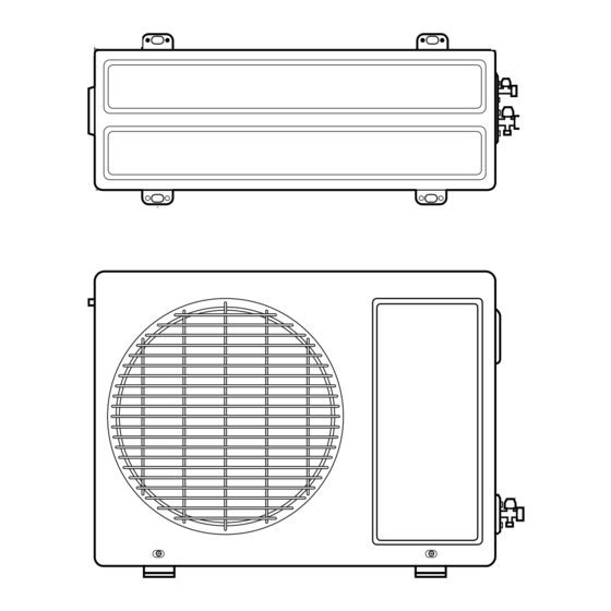
Page 10: Outdoor Unit
Outdoor Unit MODEL unit 10 Room Air Conditioner 9k, 12k Models Gas side (3-way valve) Liquid side (2-way valve) 770(30.3) 540(21.3) 245(9.6) 285(11.2) 64(2.5) 518(20.4) 10(0.4) 100(3.9) -
Page 11: Product Specifications
Product Specifications Models Cooling Capacity (Min~Rating~Max) Btu/h Heating Capacity (Min~Rating~Max) Btu/h Power Input Cooling/Heating Running Current Cooling/Heating Starting Current Cooling/Heating Btu/h.W Power Supply Ø / V / Hz Power Factor Indoor,Max /min(cfm) Air Flow Rate Outdoor,Max /min(cfm) Moisture Removal Indoor,H/M/L dB(A)+3 Sound Level Outdoor,Max... -
Page 12: Installation
Installation Read carefully, and then follow step by step. Installation Parts Installation guide map Type "B" screw Installation Tools Figure 12 Room Air Conditioner Name Screw driver Electric drill Measuring tape, Knife Hole core drill Spanner Torque wrench Type "A" screw and plastic anchor... -
Page 13: Installtion Map
Installation Map Installation parts you should purchase. NOTICE More than 19.6"(50cm) (Left and right are identical) More than More than 11.8"(30cm) 11.8"(30cm) More than 28"(70cm) More than More than More than 3.9"(10cm) 3.9"(10cm) 7.9"(20cm) Saddle More than 23.6"(60cm) More than More than 11.8"(30cm ) 11.8"(30cm ) -
Page 14: Confirm The Refrigerant
R-22 -40.8 Do not handle the pipe by yourself (customer) High-pressure refrigerant may cause personal injury. - manifold gauge ,charging and any piping tools must be dedicated to R-410A systems. 14 Room Air Conditioner 100% Vapor pressure(25°C)(kg f/cnf) 15.9 Vapor density(25°C)(kg/m... -
Page 15: Select The Best Locations
28"(70cm) of space. 3. Do not place animals and plants in the path of the warm air. 4. Take the weight of the air conditioner into account and select a place where noise and vibration are min- imum. -
Page 16: Piping Length And Elevation
Ø12.7mm(1/2") Ø6.35mm(1/4") Indoor unit Outdoor unit CAUTION: Capacity is based on standard length and maximum allowance length is on the basis of reliability. Oil trap should be installed every 16.4~23feets (5~7 meters). 16 Room Air Conditioner Standard Max. Length Elevation m(ft) m(ft) 7.5(25) -
Page 17: Preparing Work For Installation
Preparing Work for Installation Open panel front 1. Pull the upper part of the front panel. 2. Lift up the panel. 3. To detach the front panel, remove the two screws at the lower part. 4. Detach the front panel from the body. 5. -
Page 18: Fixing Indoor Unit
• Drill the piping hole with a ø50mm hole core drill. Drill the piping hole at either the right or the left with the hole slightly slanted to the outdoor side. 18 Room Air Conditioner 2. Look at suited horizon by horizontal meter on the horizontal setting line, and fix lightly the map by adhesive tape. -
Page 19: Flaring Work And Connection Of Piping
Flaring work and connection of piping Flaring Work Main cause for gas leakage is due to defect in flaring work. Carry out correct flaring work in the following procedure. Cutting the pipes and the cable. 1. Use the piping kit accessory or the pipes purchased locally. -
Page 20: Connecting The Piping
CAUTION: If the drain hose is routed inside the room, insulate the hose with an insulation material* so that dripping from "sweating"(condensation) will not dam- age furniture or floors. *Foamed polyethylene or equivalent is recommended. 20 Room Air Conditioner Smooth all round Inside is shiny without scratches = Improper flaring =... -
Page 21: Connection Of The Drain Hose
Connecting the piping with the indoor unit and drain hose with drain pipe 1. Align the center of the pipings and sufficiently tighten the flare nut by hand. 2. Tighten the flare nut with a wrench. Outside diameter inch Ø6.35 Ø9.52 Ø12.7 3. - Page 22 For right piping. Follow the instruction below. Good case • Press on the upper side of clamp and unfold the tubing to downward slowly. Bad case • Following bending type from left to right may cause damage to the turbing. 22 Room Air Conditioner...
-
Page 23: Connection Of Piping-Outdoor
Connection of Piping -Outdoor Put a couple drops of refrigerant oil on the face of the flare before assembling taking care not to add any contaminants. Align the center of the pipings and sufficiently tighten the flare nut by hand. Finally, tighten the flare nut with torque wrench until the wrench clicks. -
Page 24: Connecting The Cable Between Indoor Unit And Outdoor Unit
Power Supply AWG(MIN) Power Model source 9k/12k 1Ø, 115V 24 Room Air Conditioner Wiring Diagram Indoor Unit L1 is neutral for 115V models. NOTICE 2. Separately wire the high and low voltage line. 3. Use heat-proof electrical wiring capable of with- standing temperatures up to 167°F(75°C). -
Page 25: Connection Method Of The Connecting Cable(Example)
Connection method of the connecting cable(Example) 1. Dismount two-caps on the conduit panel. 2. Make a hole appropriate for the passage of connec- tion cable through on cap by tool. (for low voltage line) 3. Pass the connecting cable through the hole. 4. - Page 26 After the confirmation of the above conditions, prepare the wiring as follows: 1) Never fail to have an individual power circuit specifically for the air conditioner. As for the method of wiring, be guided by the circuit diagram posted on the inside of control cover.
-
Page 27: Checking The Drainage And Forming The Pipings
Checking the drainage and forming the pipings Checking the Drainage To check the drainage. 1. Pour a glass of water on the evaporator. 2. Ensure the water flows through the drain hose of the indoor unit without any leakage and goes out the drain exit. -
Page 28: Forming The Piping
2. Secure the taped piping along the exterior wall. Form a trap to prevent water entering the room. 3. Fix the piping onto the wall by saddle or equivalent. 28 Room Air Conditioner Seal small openings around pipings with a gum type sealer. -
Page 29: Air Purging
AIR PURGING Air Purging Air purging The air and moisture remaining in the refrigerant system have undesirable effects as indicated below. 1. Pressure in the system rises. 2. Operating current rises. 3. Cooling(or heating) efficiency drops. 4. Moisture in the refrigerant circuit may freeze and block capillary tubing. 5. -
Page 30: Finishing The Job
5. Replace the valve caps at both gas and liquid side ser- vice valves and fasten them tight. This completes air purging with a vacuum pump. The air conditioner is now ready to test run. 30 Room Air Conditioner Liquid side... -
Page 31: Charging
Charging Each outdoor unit is factory charged (nameplate charge) for the evaporator as well as a 7.5m(25ft) line set. Any time a line set is used either shorter or longer then the nominal 7.5m(25ft) line set length the refrigerant charge has to be adjusted. Whether the line set is made shorter or longer you must adjust the charge based on how many ft of tubing are either added or removed based on 20g(0.22oz) of R-410A per meter(foot). -
Page 32: Panel Front Assembly
2. Assemble connecting lead wire with controller, fix the upper part of panel front, and match the lower part of panel front. 3. Screw up panel front, and suspend the hook of panel front in the groove. 32 Room Air Conditioner Panel Front Connector... -
Page 33: Test Running
3. Ensure the difference between the intake tempera- ture and the discharge is more than 46.4°F(8°C) 4. For reference; the gas side pressure of optimum con- dition is as below.(Cooling) The air conditioner is now ready for use. Bolt Intake temperature Discharge air... -
Page 34: Pump Down Procedure
5. When the low-pressure gauge reading becomes 1 to 0.5kg/cm valve and then quickly turn off the unit. Now Pump Down procedure is completed, and all refrigerant is collected into the outdoor unit. 34 Room Air Conditioner G(14.2 to 7.1 P.S.I.G.), fully close the gas side... -
Page 35: How To Replace Picture & Photograph
How to replace picture & photograph Turn off power and then open the upper part of front panel. Take out picture. Cover mat and press down with hand(s) until contacting closely. In case a mat is not used, recommended size of a photo/picture: 522mm x 522mm When powering on after replacing filter and picture, the front panel doesn't intervene. -
Page 36: Operation
• The fan speed is automatically switched from high to low speed. Chaos Swing • The louver can be set at the desired position or swing up and down automatically. 36 Room Air Conditioner Defrost control(Heating) • Both the indoor and outdoor fan stops during defrosting. -
Page 37: The Function Of Main Control
The function of main control 1. Time delay Safety Control • 3min.; The compressor operation is delayed for 3 minutes to balance the pressure of cycle. (Protection of compressor) • 5sec.; The indoor fan is delayed for 5 seconds, when operating initially, to prevent noises occurred by the vertical louver and wind. - Page 38 SETTING TEMP. +1°F (Compressor OFF) SETTING TEMP. -1°F (Compressor ON) INDOOR FAN SPEED COMPRESSOR 38 Room Air Conditioner Press Start/Stop Button Select Auto Operation Mode Check the Room temperature are decided automatically by the unit electronic control. Over below 70°F 70°F...
- Page 39 Auto Operation for Dehumidification(only Heating Model) • The Setting temperature will be same that of the auto operation for cooling. - Compressor ON temperature; Setting temperature +2°F - Compressor OFF temperature; Setting temperture -1°F Intake-air temp. Setting temp. Auto Operation for Heating(only Heating Model) - Compressor ON temperature;...
- Page 40 • The indoor fan stops until the indoor pipe temperature will be reached at 82°F. • During heating operation, if indoor pipe temperature falls below 78°F fan stops. • The operation diagram is shown below. INDOOR PIPE TEMP. INDOOR FAN SPEED COMPRESSOR 40 Room Air Conditioner minimum 10sec. 1min 82°F 78°F minimum minimum 1 min.
- Page 41 7. Cooling or Heating Mode with Sleep Mode Auto Control • When selecting the Cooling( operation diagram is as following. Cooling Mode with the Sleep Mode • The setting temperature will be automatically raised by 2°F 30 minutes later and by 4°F 1 hour later. •...
-
Page 42: Helpful Information
- Press and hold the ON/OFF button for 6 seconds, then the buzzer sound 2 "beep" and the indicator lamp (1) brights 4 times. 42 Room Air Conditioner Heat pump Model Room Temp. 76°F(24°C) 70°F(21°C) Room Temp. < 76°F(24°C) Room Temp. < 70°F(21°C) -
Page 43: Display Function
Display Function Signal Receptor Receives the signals from the remote control.(Signal receiving sound: two short beeps or one long beep.) Operation Indication Lamps On/Off Self-diagnosis Function Error Error LED Code (Indoor body operation LED) (once) 3sec (twice) 3sec (5times) : Lights up during the system operation. •... -
Page 44: Remote Control Operations
Auto Operation or Auto Changeover Healthy Dehumidification Operation Heating Operation • Cooling Model( ), Heat Pump Model( 44 Room Air Conditioner 1. START/STOP BUTTON Operation starts when this button is pressed and stops when the button is pressed again. 2. OPERATION MODE SELECTION BUTTON Used to select the operation mode. -
Page 45: Disassembly
Disassembly Indoor Unit WARNING: Disconnect the unit from power supply before making any checks. Be sure the power switch is set to "OFF" 1. To remove the Grille from the Chassis. - Pull the grille bottom, the remove 2 securing screws. - Lift the both lower parts of panel front. - Page 46 - Remove the securing bolt from the motor shaft. - Pull the fan out from the motor shaft. Turbo Fan - Remove 4 screws securing motor mount from the chassis and lift up the motor mount and the bracket. Motor Mount Bolt 46 Room Air Conditioner...
-
Page 47: Schematic Diagram
Schematic Diagram Schematic Diagram Heat Pump/Cooling Only Series(Indoor Unit) Service Manual 47... -
Page 48: Heat Pump Series (Outdoor Unit)
Schematic Diagram Heat Pump Series/ Cooling Only Series (Outdoor Unit) 48 Room Air Conditioner... -
Page 49: Indoor Unit P.w.b. Assembly
Schematic Diagram INDOOR UNIT P.W.B. ASSEMBLY • P/No.: 6871A20999A (PCB ASSEMBLY, MAIN) Top View Bottom View Service Manual 49... -
Page 50: Outdoor Unit P.w.b. Assembly
OUTDOOR UNIT P.W.B. ASSEMBLY • P/No.: 6871A20901C (PCB ASSEMBLY, MAIN) Top View Bottom View 50 Room Air Conditioner... -
Page 51: Display P.w.b. Asm
Schematic Diagram DISPLAY P.W.B. ASM • P/No.: 6871A20921A (PCB ASSEMBLY) Service Manual 51... -
Page 52: Wiring Diagram
Schematic Diagram Wiring Diagram (1) Indoor Unit (Cooling Only Models, & Heating Models) 52 Room Air Conditioner... - Page 53 Schematic Diagram (2) Outdoor Unit(Cooling Only Models, & Heating Models) Service Manual 53...
-
Page 54: Troubleshooting Guide
(1) Cooling Only Models INDOOR UNIT HEAT EXCHANGE (EVAPORATOR) (2) Cooling & Heating Models INDOOR UNIT HEAT EXCHANGE (EVAPORATOR) 54 Room Air Conditioner OUTDOOR UNIT LIQUID SIDE CAPILLARY TUBE GAS SIDE OUTDOOR UNIT CHECK VALVE LIQUID SIDE CAPILLARY TUBE GAS SIDE... -
Page 55: Pipe Length And The Elevation
Piping Length and Elevation Pipe Size Capacity (Btu/h) Suction Evap 9k, 12k Ø12.7mm(1/2") Ø6.35mm(1/4") Indoor unit Outdoor unit CAUTION: Capacity is based on standard length and maximum allowance length is on the basis of reliability. Oil trap should be installed every 16.4~23feets (5~7 meters). Standard Max. -
Page 56: 3-Way Valve
Gas side Closed 3-Way valve CLOSE (6) Operate the air conditioner in cooling mode and stop it when the gauge indicates 1kg/cm (7) Immediately set the Gas side valve to the closed position. – Do this quickly so that the gauge ends up indi-... - Page 57 1) Re-air purging (Re-installation) Indoor unit Gas cylinder Refrigerant OPEN • Procedure (1) Confirm that both the liquid side valve and the gas side valve are set to the closed position. (2) Connect the charge set and a gas cylinder to the service port of the Gas side valve.
- Page 58 0 kg/cm – If there is no air in the refrigerant cycle (the pressure when the air conditioner is not running is higher than 1 kg/cm erant until the gauge indicates 0.5 to 1 kg/cm sary to apply a evacuatin.
-
Page 59: Vacuum Pump
2. Evacuation (All amount of refrigerant leaked) Indoor unit Vacuum pump OPEN • Procedure (1) Connect the vacuum pump to the center hose of charge set center hose (2) Evacuation for approximately one hour. – Confirm that the gauge needle has moved toward -76 cmHg (vacuum of 4 mmHg or less). -
Page 60: Gas Charging
(approximately 150g each time) while operating the air conditioner in the cooling cycle; however, one time is not suffi- cient, wait approximately 1 minute and then repeat the procedure (pumping down-pin). - Page 61 Additional gas charging (Gas leakage) • When refrigerant is insufficient by leakage, recharge the unit with the refrigerant up to normal operating suc- tion pressure. • Use the graph or the equation below to get operating suction pressure according to indoor and outdoor tem- perature.
-
Page 62: Cycle Parts
1. The suction pressure is usually 4.5~6.0 kg/cm 2. The temperature can be measured by attaching the thermometer to the low pressure tubing and wrap it with putty. 62 Room Air Conditioner : less than 80% of rated current : less than 80% of... -
Page 63: Electronic Parts
Electronic Parts (9k model) Product does not operate at all. (* Refer to Electronic Control Device drawing and Schematic diagram.) Does "beeping" sound is made from the Indoor Unit? Check the voltage of power(About AC 115V, 60Hz) • Main power's voltage •... -
Page 64: The Product Is Not Operate With The Remote Controller
Check the connecting circuit between the remote controller MICOM (No. ) - R17(2 ) - IR LED - Q1 - R16(2.2K ). 64 Room Air Conditioner Turn on Main Power Caused by other parts except the remote controller Check the contact of CN-DISP connector. -
Page 65: Compressor/Outdoor Fan Are Unable To Drive
Compressor/Outdoor Fan are unable to drive. Operate "Cooling Mode( remote controller is less than one of the indoor temperature by 2°F at least. When in Fan Mode, Compressor/Outdoor Fan is stopped. Check the sensor for indoor temperature is attached as close as to be effected by the temperature of Heat Exchanger(EVA). -
Page 66: When Indoor Fan Does Not Operate
Indoor Fan may be stopped in the Soft Dry Mode(change to the Cooling Operation Mode). Indoor Fan is to be stopped when Indoor pipe(coil) termperature is lower than 79°F. (At that times, Defrost indicator is turned on) 66 Room Air Conditioner Check connecting condition of the CN-MOTOR CON- NECTOR Check the interference of Indoor Fan. -
Page 67: When Vertical Louver Does Not Operate
When Vertical Louver does not operate. • Confirm that the Vertical Louver is normally geared with the shaft of Stepping Motor. • If the regular torque is detected when rotating the Vertical Louver with hands Normal • Check the connecting condition of CN-UP/DOWN Connector •... -
Page 68: When A Comunication Error Occurs
Caution: If the connecting wires of Indoor and Outdoor unit are not connected within 2 minutes after the power of Outdoor unit is applied, a communication error will occur. Therefore, the power should be applied after connecting them. 68 Room Air Conditioner... - Page 69 The phenomena in case of connecting error INDOOR UNIT Connector Type CN-DC/DC Open and connecting error Blue Black Brown CN-MOTOR CN-UP/DOWN Short between terminals CN-DISP CN-TH Short between terminals Short between terminals Condition • The same as the phenomenon of Outdoor Unit. •...
-
Page 70: Outdoor Unit
Brown Connecting error Connecting error Connecting error Connecting error 70 Room Air Conditioner • All functions stop. • The operation with the remote controller, forced and OPEN test one do not operate. • PWB pattern is damaged when applying the power. - Page 71 Voltage of Connectors according to Indoor Fan Speed INDOOR MOTOR INDOOR PWB ASSY CN-DC/DC 1 2 3 4 5 BL BK BR RD INDOOR MOTOR INDOOR DC/DC OUTDOO R CN- DC/DC Connecting wires between Indoor and Outdoor Indoor Outdoor Connecting Terminal Connecting Terminal No.
-
Page 72: Exploded View
159830 NOTE) Please ensure GCSC since the replacement parts may be changed demending upon the buyer's request. Please check the correct parts in View RPL(Replacement Part List)on GCSC. (GCSC Website http://biz.Lgservice.com) 72 Room Air Conditioner 135316 152302 145200 135515 354210... - Page 73 2. Outdoor Unit 559010 435301 NOTE) Please ensure GCSC since the replacement parts may be changed demending upon the buyer's request. Please check the correct parts in View RPL(Replacement Part List)on GCSC. (GCSC Website http://biz.Lgservice.com) 554031 549610 546810 649950 W0CZZ 268711-6 447910 437211...
-
Page 74: Replacement Parts List
Hose Assembly,Drain NOTE) Please ensure GCSC since the replacement parts may be changed demending upon the buyer's request. Please check the correct parts in View RPL(Replacement Part List)on GCSC. (GCSC Website http://biz.Lgservice.com) 74 Room Air Conditioner PART No. LAN091CNP LAN091HNP LA090CPI... - Page 75 Parts List(Outdoor) LOCATION DESCRIPTION 430410 Base Assembly,Outdoor 552203-1 Valve,Service 552203-2 Valve,Service 554031 Condenser Assembly,Bending 549610 Bracket Assembly,Motor(Outdoor) 346811 AC Motor Assembly 559010 Fan Assembly,Propeller 447910 Barrier Assembly,Outdoor 550140 Damper,Compressor 554160 Compressor Set,Korea 567502 Overload Protect 552113 Tube Assembly,Condenser(Out) 552116 Tube Assembly,Reverse 552202 Valve,Reverse 566000...
- Page 76 December, 2006 P/No.: 3828A20926C Printed in Korea...
Need help?
Do you have a question about the LAN091CNP, LAU091CNP, LAN121CNP and is the answer not in the manual?
Questions and answers