Table of Contents
Advertisement
Advertisement
Table of Contents

Related Manuals for Technics SA-DV290EE


Summary of Contents for Technics SA-DV290EE
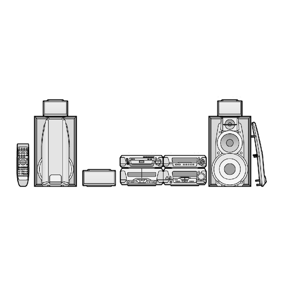
- Page 1 ORDER NO. AD0305100C8 Tuner/ Amplifier SA-DV290EE / SA-DV290GN Colour (S).......Silver Type System: SC-DV290 Because of unique interconnecting cables, when a compact requires service, send or bring in the entire system. SPECIFICATIONS Specification...
- Page 2 Amplifier section Power output (L/R both channel driven) Stereo Mode 2×25 W 1 kHz THD 1%/6 (High) 2×45 W 100 Hz THD 1%/8 (Low) RMS 1 kHz THD 10%/6 2×35 W (High) 2×65 W 100 Hz THD 10%/8 (Low) PRO LOGIC mode FRONT 2×25 W 1 kHz THD 1%/6...
- Page 3 Function Play timer (1 time, daily), Rec timer (1 time, daily) Sleep (120 min, 30 min intervals) Setting intervals (Play/Rec) 1 minute—23 hours 59 minutes (1 min intervals) General Power supply (For (GN) area) AC 230—240V 50Hz (For (EE) area) AC 230V 50Hz Power consumption 230 W...
- Page 4 (RJA0035-2X)....1 pc. - Remote control for (EE) area (EUR7702290)....1 pc. - Remote control for (GN) area (EUR7702300)....1 pc. - Remote control batteries (R6/LR6,”AA”,UM-3)....1 pc. Note: These are available on sales route.
- Page 5 - FM indoor antenna for (EE) area (N1EAYY000002)....1 pc. - FM indoor antenna for (GN) area (N1EAYY000001)....1 pc. - AM loop antenna set (N1DAEYA00008)....1 pc. - Speaker leads (REE1234-1)....2 pc. (Red/Black) (REE1233-1)....2 pc. (Gray/Blue)
- Page 6 - Video cord (K2JA2A000018)....1 pc. - RCAJ adaptor for (EE) area (K1JZ24D00002)....1 pc. 2. Before Repair and Adjustment 1. Turn off the power supply. Using a 10 , 10W resistor, connect both ends of power supply capacitors (C701-704) in order to discharge the voltage.
-
Page 7: Operating Instructions
*No sound is heard when the power is supplied. *Sound stops during a performance. The functions of this circuitry is to prevent circuitry damage, for example, the positive and negative speaker connection wires are “shorted”, or if speaker systems with an impedande less than the indicated rated impedance of thisunitareused. - Page 8 5.2. Checking for the operation P.C.B. - Follow the (Step 1) - (Step 3) of item 5.1. - Check the operation P.C.B. as shown below. 5.3. Checking for the main P.C.B.
- Page 9 - Follow the (Step 1) - (Step 3) of item 5.1.
- Page 10 - Check the main P.C.B. as shown below. 5.4. Replacement for the regulator transistor...
- Page 11 - Follow the (Step 1) - (Step 3) of item 5.1. 5.5. Replacement for the power IC - Follow the (Step 1) - (Step 3) of item 5.1. - Follow the (Step 1) - (Step 6) of item 5.2. - Follow the (Step 1) - (Step 10) of item 5.3.
- Page 12 6. Self-Diagnostic Function This unit equipped with a self-diagnostic function which, in the event of a malfunction, automatically displays a code indicating the nature of the malfunction. Use this self-diagnostic function when servicing the unit. 6.1. To display the malfunction code U70 DVD: Automatically displays on the U70 DECK: tuner/amplifier when a...
- Page 13 6.2. To return to the normal display 1. For U70 DVD/U70 DECK - Press an any operation button on the tuner/amplifier. - To re-display the code, switch the power off (POWER STANDBY button), and then switch power back on again. 2.
- Page 14 - If U70 is displayed on the tuner/amplifier, the Cassette deck or DVD Changer cannot be operated by remote control. - Correction Procedure 1. To check for correct insertion of the flat cables. - Insert each connectors until you hear a click. - Insert the flat cables at the back of the unit in the order indicated.
- Page 15 - Correction procedure Faulty Tuner/Amplifier (SA-DV290) output IC (IC601). (When a DC voltage is applied to speaker terminals.) 7. To Supply Power Source This unit SA-DV290 is designed to operate on power supplied form system connected. For system connection, refer to Fig. 7-1. Fig.
- Page 16 Notes: Use only this method when checking the voltage etc.. In case of checking operations, use the system connections to supply power source. 8. Schematic Diagram Notes 8.1. Type Illustration of IC's, Transistors and Diodes 8.2. Schematic Diagram Notes - This schematic diagram may be modified at any time with the development of new technology.
- Page 17 - S913: Digital super woofer (DIGITAL S. WOOFER) switch. - S914, 915: RDS display mode (RDS, PS-DISP, MODE-PTY) switches. For [EE] area. S914, 915: KARAOKE, Voice mute (KARAOKE, V.MUTE) switch. For [GN] area. - S916: Key control (KEY CON) switch. For [GN] area. - S917: MIC effect (MIC EFFECT, LOUNGE) switch.
-
Page 18: Schematic Diagram
9. Schematic Diagram 10. Printed Circuit Board Diagram 11. Block Diagram 12. Wiring Connection Diagram 13. Terminal Function of ICs 13.1. IC901 (C2BBFD000404): System Control/FL Drive Function Terminal Name CHECK Clock check signal input LC72 DO PLL data signal output for tuner unit (Z101) LC72 CE Chip enable signal output... - Page 19 Function Terminal Name SH REQ Request signal output to Sound Processor 22 NC(GND) — Not used, connected to GND Volume control signal input JOGB JOGA MIC DET Microphone connecting detect signal input (Not used, connected to V HP SW Headphone connecting detect signal input RDS clock signal input RDS data signal input...
- Page 20 Function Terminal Name 85 CHORUS — LED (CHORUS) drive signal output (Not used, connected to V MUTE Muting signal output — Not used, oppen POWER Power control signal output — GND terminal Power supply terminal MUTE2 Muting signal output — Not used, open MUTE3 Muting signal output...
- Page 21 (GN) RKW0581-1V FL WINDOW RMF0284 CUSHION (GN) RMN0427A CABLE HOLDER RYP1168-S FRONT PANEL ASS’Y (EE) RYP1168A-S FRONT PANEL ASS’Y (GN) 13-1 RGB0025-A TECHNICS BADGE 13-2 RGU1748-Q BUTTON,MIC EFFECT (GN) SHG1654 RUBBER XTB3+10JFZ SCREW XTB3+20JFZ SCREW XTB3+8JFZ SCREW XTW3+15T SCREW XTB3+12FFZ...
- Page 22 Ref. No. Part No. Part Name & Description Remarks EUR7702290 REMOTE CONTROL (EE) EUR7702300 REMOTE CONTROL (GN) A1-1 UR64EC2337E BATTERY COVER K2JA2A000018 VIDEO CORD REE1233-1 SPEAKER LEADS(GRAY/BLUE) REE1234-1 SPEAKER LEADS(RED/BLACK) RJA0019-2X AC MAINS LEAD (EE) RJA0035-2X AC MAINS LEAD (GN) RQCA0801 QUICK SET-UP GUIDE RQT6895-R...
- Page 23 Ref. No. Part No. Part Name & Description Remarks C601,02 ECA1CAK100XB 16V 10U C603,04 ECBT1H471KB3 50V 470P C605,06 ECBT1H102KB3 50V 1000P C607,08 ECBT1H471KB3 50V 470P C609,10 ECBT1H560J3 50V 56P C611 F1D1H390A006 50V 39P C612 ECBT1H150JC3 50V 15P C613,14 ECBT1H470J3 50V 47P C616 ECEA1HKNR47B 50V 0.47U...
- Page 25 Ref. No. Part No. Part Name & Description Remarks C901 EEAFC0J101B 6.3V 100U C902 F2A1A102A018 10V 1000U C903,04 ECBT1H103KB5 50V 0.01U F1E1H1030001 C905 ECBT1H102KB3 50V 1000P C907,08 ECBT1H471KB3 50V 470P C909 ECBT1H102KB3 50V 1000P C910 ECBT1H200JC5 50V 20P F1D1H200A015 C911 F1D1H180A006 50V 18P C912...
- Page 26 Ref. No. Part No. Part Name & Description Remarks D730 MA4091H DIODE MAZ40910H D737 MA4082LTA DIODE MAZ40820LF D738-40 MA165TA5 DIODE MA2C16500E D741-44 B0AAMM000009 DIODE D745 MA4051M DIODE MAZ40510M D746 B0AAMM000009 DIODE D747 MA4068L DIODE MAZ40680L D751,52 1N5402BF DIODE D753-55 B0AAMM000009 DIODE D756,57 MA700...
- Page 28 Ref. No. Part No. Part Name & Description Remarks RPG4396 PACKING CASE(SA) RPG4397 PACKING CASE(RS) RPG4398 PACKING CASE(SH) RPG4399 PACKING CASE(SL) RPN1194 POLYFOAM(SA) RPN1195-2 POLYFOAM(RS) RPN1196 POLYFOAM(SH) RPN1197 POLYFOAM(SL) SPP740-1 PROTECTION COVER RPF0139-1 PROTECTION BAG(ACCESS.) RPG6349 PACKING CASE(SYSTEM) (EE) RPG6350 PACKING CASE(SYSTEM) (GN) RPQ0951...
- Page 29 Ref. No. Part No. Part Name & Description Remarks R404 ERDS2FJ471 1/4W 470 (GN) R405 ERDS2FJ472 1/4W 4.7K (GN) R406 ERDS2FJ474 1/4W 470K (GN) R407 ERDS2FJ472 1/4W 4.7K (GN) R409 ERDS2FJ472 1/4W 4.7K (GN) R410 ERDS2FJ222 1/4W 2.2K (GN) R411 ERDS2FJ331 1/4W 330 (GN)
- Page 30 Ref. No. Part No. Part Name & Description Remarks R649-52 ERDS1FJ100 1/2W 10 R683-86 ERDS2FJ102 1/4W 1K R687,88 ERDS2FJ152 1/4W 1.5K R691 ERDS1FJ680 1/2W 68 R692,93 ERDS2FJ102 1/4W 1K R694 ERDS2FJ223 1/4W 22K R695 ERDS2FJ471 1/4W 470 R696 ERDS2FJ473 1/4W 47K R708 ERDS2FJ472 1/4W 4.7K...
- Page 31 Ref. No. Part No. Part Name & Description Remarks R914 ERDS2FJ102 1/4W 1K R915 ERDS2FJ122 1/4W 1.2K R916 ERDS2FJ152 1/4W 1.5K R918 ERDS2FJ103 1/4W 10K R919 ERDS2FJ153 1/4W 15K R921,22 ERDS2FJ103 1/4W 10K R924,25 ERDS2FJ102 1/4W 1K R926 ERDS2FJ222 1/4W 2.2K R928 ERDS2FJ473 1/4W 47K...
- Page 32 T701 ETP76VST617A POWER TRANSFORMER T702 ETP28KBZ21BG POWER TRANSFORMER VR401 EVUE27FK3B53 V.R.,MIC VOLUME (GN) VR901 EVQVBXFK124B V.R.,VOLUME X151 H0H433400001 OSCILLATOR (EE) X901 EF0EC6004T4 OSCILLATOR EFOEC6004T4 X902 H0A327200027 OSCILLATOR Z701 ENC471D5A J0LG00000008 Z901 B3RAD0000028 REMOTE SENSOR 15. Cabinet Parts Location 15.1. SA-DV290EE...
- Page 33 15.2. SA-DV290GN...
- Page 34 16. Packaging...
- Page 35 17. Schematic Diagram for printing with A4 size K0305 YH/HM...
-
Page 36: Main Circuit
: POSITIVE VOLTAGE LINE FAN MOTOR MAIN CIRCUIT : NEGATIVE VOLTAGE LINE :AUDIO SIGNAL LINE 7.6V 7.6V -10.4V Q556 JK551 2SC5398RSTA IC601 MOTOR DRIVE R566 RSN311W64B 4.7V FAN ON:0V 0.5V POWER AMP FAN ON:0V R568 C556 0.5V R570 16V10 2.2M Q557 C552 R559... -
Page 37: Ac In Circuit
: POSITIVE VOLTAGE LINE : NEGATIVE VOLTAGE LINE MAIN CIRCUIT AC IN CIRCUIT : AUDIO SIGNAL LINE CN601 L605 SPEAKERS JK603 R649 JK601 C OUT CENTER(8 ) C OUT L604 HF(6 L602 R644 SPEAKERS R ch R640 SUR L IN L603 SUR L IN SURROUND(8 ) - Page 38 OPERATION CIRCUIT FL901 (A2BB00000115) FL DISPLAY 10 11 12 13 14 15 16 17 18 19 20 21 22 23 24 25 26 27 28 29 30 31 32 33 34 35 36 37 38 39 40 41 42 43 44 45 46 47 48 49 50 53 54 R996 A B C D...
- Page 39 : POSITIVE VOLTAGE LINE : NEGATIVE VOLTAGE LINE :AUDIO SIGNAL LINE :MIC SIGNAL LINE -30.1V A B C D E F G H I J K L M N O P Q R S T U V W X 5.1V Q901 For [GN] area.
- Page 40 : NEGATIVE VOLTAGE LINE :AUDIO SIGNAL LINE :MIC SIGNAL LINE OPERATION CIRCUIT : POSITIVE VOLTAGE LINE :TUNER SIGNAL LINE TUNER Lch/ TUNER Rc A.GN Lch I +B(10V 5.1V R941 VR901 EVQVBXFK124B (VOLUME) Z901 SOUND B3RAD0000028 Q902 PROCESSOR -B(-10V (REMOTE SENSOR) UN411FTA (SH-DV290) V.GN...
- Page 41 MAIN CIRCUIT 7.6V -10.4V W501 TUNER Lch/C TUNER Rch R511 R509 R597 C659 R631 A.GND 2.2K 16V10 3.9K Lch IN R512 47 R510 Rch IN C660 +B(10V) R598 R632 10.4V 16V10 3.9K 2.2K SUR L C202 SUR R SOUND PROCESSOR -B(-10V) -10.4V (SH-DV290)
- Page 42 : POSITIVE VOLTAGE LINE MAIN CIRCUIT : NEGATIVE VOLTAGE LINE :AUDIO SIGNAL LINE 7.6V -10.4V IC601 RSN311W64B POWER AMP -51.4V 54.1V -29.7V 29.4V -0.2V -29.3V 28.9V -59.5V 59.5V C648 1000P R612 C610 R620 120K R611 C609 R619 120K R610 150K R603 C612 R622...
- Page 43 FAN MOTOR 7.6V Q556 JK551 2SC5398RSTA MOTOR DRIVE R566 4.7V 0.5V FAN ON:0V FAN ON:0V R568 C556 0.5V R570 16V10 2.2M Q557 C552 R559 7.6V 2SA1995RSTA 0.01 4.7K -10.4V MOTOR DRIVE -10.4V -10.4V 0.3V R558 R591 Q555 2.2K 4.7K 2SD2144STA Q551 Q554 SIGNAL LEVEL DET.
- Page 44 : POSITIVE VOLTAGE LINE : NEGATIVE VOLTAGE LINE MAIN CIRCUIT : AUDIO SIGNAL LINE L605 SPEAKERS R649 JK601 HF(6 L602 R640 LF(8 L606 R650 JK602 HF(6 LF(8 L601 CP601 R639 C OUT C OUT SUR L OUT SUR L OUT SUR R OUT SUR R OUT CP602...
- Page 45 AC IN CIRCUIT CN601 JK603 C OUT CENTER(8 ) C OUT L604 R644 SPEAKERS R ch SUR L IN L603 SUR L IN SURROUND(8 ) SUR R IN R643 SUR R IN L ch R795 3.9K CN602 R712 2.2K SH SYNC SA SYNC D.GND Q726...
- Page 46 BU4053BCFE2 C2BBFD000404 RSN311W64B TA2011S 2SB1417PQTA 2SD2144STA C1BB00000527 2SD2137PQTA ....... 2SA1995RSTA 2SC3940AQSTA 2SB1548PQAU UN411FTA...
- Page 47 FAN MOTOR For [GN] area. To SOUND PROCESSOR SPEAKERS MIC1 MIC2 JK551 MIC JACK Z101 CP601 P.C.B. TUNER PACK W904B CP101 1 . . 4 MAIN P.C.B. CP602 ..W501 ..
- Page 49 W501 TUNER L/C FM ANT TUNER Rch A.GND BU4053BCFE2 IC201 Lch IN SIGNAL SELECTOR Rch IN Z101 TUNER PACK AM ANT RAN0005EM-2:EE +B(10V) ENG06502Q:GN SUR L SUR R SW CONT. To SOUND PROCESSOR BLOCK DIAGRAM -B(-10V) V.GND For [EE] area. D.GND CS/REQ C1BB00000527...
- Page 50 PHONES R ch RSN311W64B IC601 Q609 Q607 POWER AMP (18) (Q610) (Q608) MUTING MUTING Q606 MUTING D974 D601 POWER CONTROL CIRCUIT (25) Q605 SURROUND MUTING CENTER SPEAKERS Q902 Q612 (12) MUTING MUTING CONT. CONT. Q503,D558 SWITCH- POWER CONTROL/ PROTECTION CIRCUIT Q551,554, SIGNAL LEVEL DET.
- Page 51 Q702,705 REGULATOR T701 /STABILIZER D702,704, 752,754,755 D701,703, 751,753,761 Q703,704 REGULATOR Q723 NOTES : SIGNAL LINE L701 : AUDIO SIGNAL REGULATOR : TUNER SIGNAL Q701 AC IN : MIC SIGNAL Z701 REGULATOR RL702 ) indicates pin No. Right channel. AC IN D718,720 FP791 Q711,712,725...
- Page 52 Note: This printed circuit board diagram may be modified at any time with the development of new technology. MAIN P.C.B. OPERATION P.C.B. Q723 C740 D737 VR901 W902A (VOLUME) CP101 CN781 W902B Q609 R693 E C B [GN] area. R692 W501 E C B S913 R597...
- Page 53 POWER SUPPLY P.C.B. POWER TRANSFORMER (A) P.C.B. POWER TRANSFORMER R725 Q701 C717 (B) P.C.B. R723 T701(Power transformer) W701B Q705 CN701 E C B [GN] area. R794A Q702 CN711 CN702 R793 [EE] area. CN703 R749 W721B W722B Q711 CN713 CN704 Q725 CN705 R765 D730...
- Page 54 OPERATION CIRCUIT : POSITIVE VOLTAGE LINE : NEGATIVE VOLTAGE LINE :AUDIO SIGNAL LINE :MIC SIGNAL LINE -30.1V FL901 (A2BB00000115) A B C D E F G H I J K L M N O P Q R S T U V W X FL DISPLAY 10 11 12 13 14 15 16 17 18 19 20 21 22 23 24 25 26 27 28 29 30 31 32 33 34 35 36 37 38 39 40 41 42 43 44 45 46 47 48 49 50 53 54...
- Page 55 : NEGATIVE VOLTAGE LINE :AUDIO SIGNAL LINE :MIC SIGNAL LINE MAIN CIRCUIT OPERATION CIRCUIT : POSITIVE VOLTAGE LINE :TUNER SIGNAL LINE 7.6V -10.4V W501 TUNER Lch/C TUNER Rch R511 R509 R597 C659 R631 A.GND 2.2K 16V10 3.9K Lch IN R512 47 R510 Rch IN C660...
Need help?
Do you have a question about the SA-DV290EE and is the answer not in the manual?
Questions and answers