
Related Manuals for TYM MM60


Summary of Contents for TYM MM60
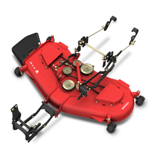
- Page 1 MODEL MID MOWER 60" MOWER AND MOUNTING INCLUDES OPERATOR'S MANUAL INSTALLATION INSTRUCTIONS AND PARTS CATALOG MODEL NAME : MM60...
- Page 2 SAFETY DECALS The safety of the operator was the prime consideration on the design of the mower. Proper shielding,convenient controls,simple adjustments,and other safety features have been built into this implement. The following decals are located on the mower deck. Keep decals clean and replace them immediately if they are missing or damaged.
- Page 3 INFORMATIONAL DECALS Part NO : JHM 1000-074-100 Part NO : JHM 1000-073-100...
- Page 4 LUBRICATION NOTICE: It is not recommended to use a preassure washer to clean the mower assembly. High pressure water may cause damage to spindles, pulleys, belts, or bearings shortening life and reducing serviceability. Life of the mower depends upon the maintenance given. Proper lubrication is very important. Always lubricate the deck and lift components before operation.
- Page 5 MOWER DECK SERVICE PARTS...
- Page 6 MOUNT KIT SERVICE PARTS BREAKDOWN PART DESCRIPTION MID MOWER WELDING ASSY JHM 1000-015-100 GEAR BOX SUB ASSY JHM 1000-002-101 VELT COVER WELDING ASSY_LH JHM 1000-021-100 JHM 1000-020-100 VELT COVER WELDING ASSY_RH FRONT WHEEL JHM 1000-024-100 CHUTE WELDING ASSY JHM 1000-011-100 RUBBER PLATE JHM 1000-010-102 JHM 1000-010-101...
- Page 7 MOUNT KIT SERVICE PARTS BREAKDOWN PART DESCRIPTION H200-100-002 Flat Washer_M12 H300-100-005 Flat Washer_M24 JHM 1000-078-100 Clip_Pin JHM 1000-029-100 Key_6 X 6 Key_5 X 5 JHM 1000-028-100 Lock Nylon Nut_M14 H200-100-003 Flat Washer_M14 H300-100-003 H900-100-001 Grease Fitting_PT 3/8...
- Page 8 TRACTOR FRONT FRONT MOUNT HANGER PLATE INSTALLATION TRACTOR FRAME 1. Tractor on the front as shown in the illustration inside the frame parts (1 & 2) and install it. Bolt M16 X 45mm (36), using the four fixing plates and washers (43) and two M16 nuts (56) to assemble.
- Page 9 REAR MOUNT ASSEMBLY INSTALLATION 1. ANCHOR SUB ASSY-LH (18) and the frame holes to match the tractor. Bolt M12 X L45 (38) and washers M12 (45) and fit the bracket to the frame preserver. Washer M12 (45) and nut M12 (50) and then replacing the assembly.
- Page 10 LOWER MOUNT LINK ASSEMBLY 1. MOVING WELDING ASSY-2 welded structures (5), and the front link weldment (4) using the four bolts to assemble. M14 X 40mm Bolt (37), washers (44) and nuts (49) and shown to assemble. Tractor mower deck is installed in the end will be adjusting.
- Page 11 REAR LIFT ASSEMBLY 1 As shown in the figure the lift pin (28) to assemble and also, the rotation link (15) with washer (41) and a split pin (54) is used to fix it. 2 As shown in the figure lifts the pin (28) to assemble and LH, rotary link (13), a washer 41 and a split pin (54) is used to fix it.
- Page 12 REAR LIFT INSTALLATION 1 under the tractor to push the link pin bushings RH rear lift (23) to install. Flat washers (59), insert four bolts M10 (40), nut (51) with the screws. 1 under the tractor to push the link pin bushings RH rear lift (24) to install.
-
Page 13: Height Adjustment
HEIGHT ADJUSTMENT 1 Together to raise the floor to hear the ring (34) and retaining pin (26) and remove the retaining pin to remove it. Distance adjustment plate to the desired position by sliding it to the left position. Locking pin (26), ring (34) to assemble. - Page 15 MOUNT KIT SERVICE PARTS BREAKDOWN PART DESCRIPTION FIXING PLATE-LH JHM 1000-056-100 FIXING PLATE-RH JHM 1000-057-100 MOVING WELDING ASSY-1 JHM 1000-030-100 JHM 1000-031-100 MOVING WELDING ASSY-2 MOVING WELDING ASSY-3 JHM 1000-032-100 DISTANCE ADJUSTMENT PLATE WELDING ASSY JHM 1000-088-100 ANCHOR BRACKET WELDING ASSY JHM 1000-086-100 JHM 1000-046-100 STOP PLATE SUB ASSY...
- Page 16 MOUNT KIT SERVICE PARTS BREAKDOWN PART DESCRIPTION Lock Nylon Nut_M14 H200-100-003 Lock Nylon Nut_M12 H200-100-004 Flat Washer_M16 H400-100-004 H300-100-003 Flat Washer_M14 Flat Washer_M12 H200-100-002 Flat Washer_M32 H300-100-006 Flat Washer_M32 H300-100-006 H200-100-005 Nut,Hex_M16 Nut,Hex_M14 H200-100-006 Nut,Hex_M12 H200-100-002 Nut,Hex_M10 H200-100-001 COTTOR_D2XL25 JHM 1000-095-100 COTTOR_D4XL25 JHM 1000-096-100 COTTOR_D5XL30...
Need help?
Do you have a question about the MM60 and is the answer not in the manual?
Questions and answers
how do you level the TYM mid mount mower deck