Table of Contents
Advertisement
Quick Links
Advertisement
Table of Contents

Related Manuals for Channel Safety Systems Zerio Plus


Summary of Contents for Channel Safety Systems Zerio Plus
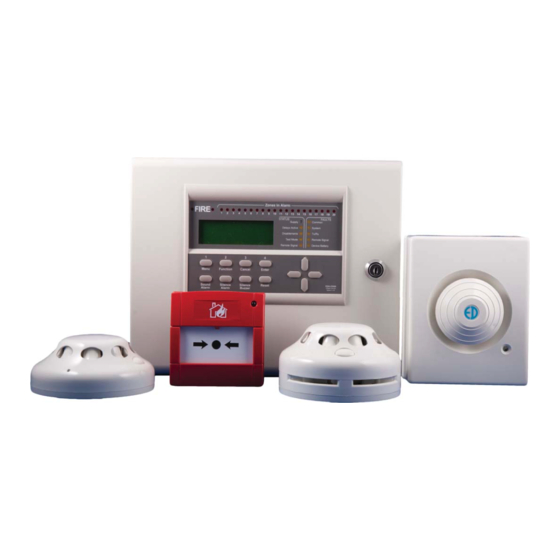
- Page 1 Zerio Plus Wireless system from Channel Safety Systems CHANNEL SAFETY SYSTEMS t: 0845 884 7000 Petersfi eld Business Park f: 0845 884 6000 Bedford Road Petersfi eld Hampshire e: sales@channelsafety.co.uk GU32 3QA w: www.channelsafety.co.uk INSTRUCTION MANUAL...
- Page 2 0845 884 7000 | w: www.channelsafety.co.uk INTRODUCTION Zerio Plus has been designed to be capable of handling 240 devices in 100 zones. Typical installations would include small offi ces, private houses, HMO’s, guest houses and small hotels. This manual contains information to enable an engineer to install, service and operate the Zerio Plus control panel and the range of Zerio Plus devices.
- Page 3 Operating Frequency 8 68MHz (868.025 to 868.575MHz) Modulation 2-GFSK Output Power (ERP) <25mW (<14dBm) Channel Spacing 50KHz Error Checking Error Correction Hamming Number Of Channels Available Compatible With Zerio Plus products only Protocol ZPNet V1.00 INSTRUCTION MANUAL - Issue 1 - 07/2014...
-
Page 4: Table Of Contents
6.22 Add Antenna 16.0 Maintenance 6.23 Add Repeater/Booster Panel 17.0 Component Replacement 6.24 Add Pager 18.0 Zerio Plus Compatible Hardware 6.25 Remove Hardware 6.26 Panel Network 6.27 Network Auto Confi gure 6.28 Device Information INSTRUCTION MANUAL - Issue 1 - 07/2014... -
Page 5: En54 Approved Configuration
1.0 - EN54 APPROVED CONFIGURATION The Zerio Plus system has been approved by Intertek to meet EN54 parts 2 and 4. The panels were tested and approved in their default confi guration. This manual lists all available panel options and settings, some of which can be set in a way that would result in a system that does not comply with EN54. -
Page 6: Installation
CHANNEL SAFETY SYSTEMS t: 0845 884 7000 | w: www.channelsafety.co.uk 2.0 - INSTALLATION The electronic components within the panel are vulnerable to electrostatic discharges. It is advisable to wear a wrist strap designed to prevent the build-up of static charges within the body before handing any electronic components. - Page 7 CHANNEL SAFETY SYSTEMS t: 0845 884 7000 | w: www.channelsafety.co.uk Battery In order to meet EN54 Part 4, a Yuasa NP7-12 lead acid battery should be fi tted. This will give a 72 hour standby, assuming no external equipment (eg wired antennas) has been added. If only 24 hours standby is required and no external equipment has been fi tted then a 12V 2.8Ahr battery could be fi tted.
- Page 8 CHANNEL SAFETY SYSTEMS t: 0845 884 7000 | w: www.channelsafety.co.uk PCB Layout Monitored Inputs The panel features two monitored inputs that can be programmed either as latching or non-latching. It is impor- tant to note that before using these inputs they must be enabled by programming them in the panel options menu.
- Page 9 CHANNEL SAFETY SYSTEMS t: 0845 884 7000 | w: www.channelsafety.co.uk Panel Relays The panel is equipped with four programmable relays, each capable of supplying 500mA. The total current draw across all four relays must not exceed 1A. The default relay types are: Relay 1: Fire Routing Relay - This activates on an alarm condition.
-
Page 10: Front Panel Layout
CHANNEL SAFETY SYSTEMS t: 0845 884 7000 | w: www.channelsafety.co.uk 3.0 - FRONT PANEL LAYOUT Fire LEDs In a fi re condition, these LEDs will fl ash. Zone Alarm LEDs In a fi re condition, the appropriate zone LED will illuminate. If the fi re condition exists across multiple zones, multiple zone LEDs will be illuminated. - Page 11 CHANNEL SAFETY SYSTEMS t: 0845 884 7000 | w: www.channelsafety.co.uk Cancel Used to return to the main screen from a menu or to return to the menu from a programming screen. Enter This is used to accept information programmed into the panel.
-
Page 12: User Operation
CHANNEL SAFETY SYSTEMS t: 0845 884 7000 | w: www.channelsafety.co.uk 3.0 - USER OPERATION 4.1 - System Normal In normal operation the screen will show either the date and time, or the supplier/service contact details. The unit can also be confi gured to alternate between the two. -
Page 13: Silence The Alarm
CHANNEL SAFETY SYSTEMS t: 0845 884 7000 | w: www.channelsafety.co.uk 4.6 - Silence the Alarm When it is certain that it is safe to return to the building the Silence Alarm button should be pressed. The user will then be prompted to enter a valid user access code using the navigation keys. Up to 30 seconds should then be allowed for all sounders to silence. -
Page 14: Menu Operation
CHANNEL SAFETY SYSTEMS t: 0845 884 7000 | w: www.channelsafety.co.uk 5.0 - MENU OPERATION To enter the menu system, press Menu. This will display an overview of any alarms, faults, disablements or tests that are currently active, along with an option to access the Main Menu. The options available on the main menu and sub-menus will be dependent on the access code entered and its corresponding access level. -
Page 15: Setup Menu
Press Enter to accept or Cancel to exit. The Zerio Plus panel automatically adjusts the clock for daylight savings. Should complete power be lost the panel will revert the time back to the default of 01/01/2013 12:00:00 6.2 - View Access Codes –... -
Page 16: Programming Agent Details
CHANNEL SAFETY SYSTEMS t: 0845 884 7000 | w: www.channelsafety.co.uk 6.4 - Programming Agent Details – service and commissioning users 1.Main Menu>>1.Setup>>3.Panel Display The system normal screen can be adjusted to display either the date and time, the agent’s name and telephone number or alternating between the two every 4 seconds. - Page 17 CHANNEL SAFETY SYSTEMS t: 0845 884 7000 | w: www.channelsafety.co.uk Panel Readings – service and commissioning users 1.Main Menu>>1.Setup>>4.System Setup>>1.Panel Info>>2.Panel Readings IP1: The resistance level on input 1. IP2: The resistance level on input 2. OP1: The resistance level on output 1.
-
Page 18: Set Up A New System (Standard)
CHANNEL SAFETY SYSTEMS t: 0845 884 7000 | w: www.channelsafety.co.uk 6.6 - Set up a New System (Standard) – commissioning users 1.Main Menu>>1.Setup>>4.System Setup>>2.New Setup>>1.Standard System Devices are programmed via a radio link to the control panel. If the system is known to have been used before then all the devices that are logged on to the system must be removed fi rst. -
Page 19: Set Up A New System (Hmo)
CHANNEL SAFETY SYSTEMS t: 0845 884 7000 | w: www.channelsafety.co.uk 6.7 - Set up a New System (HMO) – commissioning users 1.Main Menu>>1.Setup>>4.System Setup>>2.New Setup>>2.HMO System The HMO setup reduces disruption to residents in other fl ats by false alarm. Note that the HMO setup is not EN54 approved. Upon activation within a fl at, an alert tone will be sounded in that fl at. -
Page 20: User Options
CHANNEL SAFETY SYSTEMS t: 0845 884 7000 | w: www.channelsafety.co.uk 6.8 - User Options – commissioning users 1.Main Menu>>1.Setup>>4.System Setup>>3.Edit Panel>>1.Panel Options>>1.User Options Detailed below are the other options that can be changed related to the panel. The default settings have been type approved. -
Page 21: System Options
CHANNEL SAFETY SYSTEMS t: 0845 884 7000 | w: www.channelsafety.co.uk 6.9 - System Options – commissioning users 1.Main Menu>>1.Setup>>4.System Setup>>3.Edit Panel>>1.Panel Options>>2.System Options This menu allows the user to change overall system settings. Alarm Verify Time (seconds) that a device has to be in alarm to generate an alarm condition on the panel. -
Page 22: Hmo Zones
CHANNEL SAFETY SYSTEMS t: 0845 884 7000 | w: www.channelsafety.co.uk 6.11 - HMO Zones – commissioning users 1.Main Menu>>1.Setup>>4.System Setup>>3.Edit Panel>>1.Panel Options>>4.HMO Zones Use the keys to select the zone, and press Enter to change the zone type. Zones can be designated as either common zones or dwelling zones. -
Page 23: User Relays
CHANNEL SAFETY SYSTEMS t: 0845 884 7000 | w: www.channelsafety.co.uk 6.15 - Input Options – commissioning users 1.Main Menu>>1.Setup>>4.System Setup>>3.Edit Panel>>2.Panel Inputs>>1.Input Options This menu allows the user to set options for the two monitored inputs. The default settings have been type approved. -
Page 24: Panel Text
CHANNEL SAFETY SYSTEMS t: 0845 884 7000 | w: www.channelsafety.co.uk 6.18 - Panel Text – commissioning users 1.Main Menu>>1.Setup>>4.System Setup>>3.Edit Panel>>3.Panel Text This menu allows the user to set a name and/or location for the panel. This will be displayed on the system normal screen. Enter text using the panel keys or by connecting a standard USB keyboard. -
Page 25: Add Antenna
CHANNEL SAFETY SYSTEMS t: 0845 884 7000 | w: www.channelsafety.co.uk 6.22 - Add Antenna – commissioning users 1.Main Menu>>1.Setup>>4.System Setup>>5.Add Hardware>>1.Add Antenna Power down the panel before connecting the wired antenna. Once powered up, check that the supply light is illuminated on the antenna and that the status light is fl ashing. -
Page 26: Panel Network
CHANNEL SAFETY SYSTEMS t: 0845 884 7000 | w: www.channelsafety.co.uk 6.26 - Panel Network In a traditional setup, all radio booster panels will communicate directly with the main panel. The system also has the capability for the signal to ‘hop’ , as shown below. In this example the signal from radio booster 3 hops back to the main panel via radio booster 2. -
Page 27: Device Information
CHANNEL SAFETY SYSTEMS t: 0845 884 7000 | w: www.channelsafety.co.uk 6.28 - Device Information View Device Info – service and commissioning users 1.Main Menu>>1.Setup>>5.Device Setup>>1.Device Info>>1.View Device Info This menu allows the user to select a device and see all available... -
Page 28: Add Device
CHANNEL SAFETY SYSTEMS t: 0845 884 7000 | w: www.channelsafety.co.uk 6.29 - Adding a Device – commissioning users 1.Main Menu>>1.Setup>>5.Device Setup>>2.Add Device Additional devices can be added to the system at any time. The device needs to be put into programming mode in order to add it to the system. -
Page 29: Remove All Devices
CHANNEL SAFETY SYSTEMS t: 0845 884 7000 | w: www.channelsafety.co.uk 6.30 - Remove a Device – commissioning users 1.Main Menu>>1.Setup>>5.Device Setup>>3.Remove Device>>1.Remove One Device If a device is not required on the system it must be deleted to prevent it causing a verify fault once powered down. -
Page 30: Reprogram Device
CHANNEL SAFETY SYSTEMS t: 0845 884 7000 | w: www.channelsafety.co.uk 6.34 - Reprogram Device – commissioning users 1.Main Menu>>1.Setup>>5.Device Setup>>5.Reprogram Device Some settings such as operating mode, sensitivity, volume, device alarm verifi cation period and sounder area are stored on the device rather than the control panel. In order to change these settings the device will need to be put into programming mode. -
Page 31: Disable/Enable Menu
CHANNEL SAFETY SYSTEMS t: 0845 884 7000 | w: www.channelsafety.co.uk 7.0 - DISABLE/ENABLE Disable a Zone – all access levels 1.Main Menu>>2.Disable/Enable>>1.Disable>>1.Zone If a zone is disabled the system will not display any fi re or fault events for devices located in that zone. This includes any call point activations. Select the zone number to be disabled and press the key. - Page 32 CHANNEL SAFETY SYSTEMS t: 0845 884 7000 | w: www.channelsafety.co.uk Disable Sounders – all access levels 1.Main Menu>>2.Disable/Enable>>1.Disable>>4.Sounders The sounders can be disabled for a period of time specifi ed by the user, dependent on their access level. All access levels can disable a sounder for a period of 1 to 96 hours.
- Page 33 CHANNEL SAFETY SYSTEMS t: 0845 884 7000 | w: www.channelsafety.co.uk Enable a Zone – all access levels 1.Main Menu>>2.Disable/Enable>>2.Enable>>1.Zone To enable a previously disabled zone, select it using the or keys and press Enter. To enable more zones press Enter, or Cancel to exit. If all zones have been enabled ‘No Zones to enable’ will be displayed. If a disabled zone is enabled;...
-
Page 34: Test Mode
CHANNEL SAFETY SYSTEMS t: 0845 884 7000 | w: www.channelsafety.co.uk 8.0 - TEST MODE Test mode allows a system to be tested with minimal disruption to the occupants of a building. When a zone is placed into test mode the engineer can choose to disable sounders, actuators or any output devices. -
Page 35: Disable System Test
CHANNEL SAFETY SYSTEMS t: 0845 884 7000 | w: www.channelsafety.co.uk 8.3 - Lamp/Buzzer Test – advanced, service and commissioning users 1.Main Menu>>3.Test Mode>>3.Lamp/Buzzer Test This option will illuminate all the panels LEDs in sequence, to check they are working properly. The panel buzzer will also sound. -
Page 36: Event Log
CHANNEL SAFETY SYSTEMS t: 0845 884 7000 | w: www.channelsafety.co.uk 9.0 - EVENT LOG 9.1 - View Alarm Count – advanced, service and commissioning users 1.Main Menu>>4.View Events>>1.View Alarm Count Select this option to view the total number of times the panel has entered the alarm condition since the system was installed. -
Page 37: Verify Table
CHANNEL SAFETY SYSTEMS t: 0845 884 7000 | w: www.channelsafety.co.uk 10.0 - VERIFY TABLE Verify and Signal Strengths 1.Main Menu>>5.Verify Table The verify information is essential to the engineer to ensure the system is set-up correctly. It details signal strengths and performance information about all of the devices on the system. Each device regularly sends out verify messages to the main panel. -
Page 38: View Detailed
CHANNEL SAFETY SYSTEMS t: 0845 884 7000 | w: www.channelsafety.co.uk 10.2 - View Detailed Verify Information for a Single Device – service and commissioning users 1.Main Menu>>5.Verify Table>>1.View Table>>2.View Detailed From the ‘Verify Table’ menu, select ‘1-View Table’ . Select ‘2View Detailed’ . -
Page 39: View Panel Table
CHANNEL SAFETY SYSTEMS t: 0845 884 7000 | w: www.channelsafety.co.uk 10.3 - Clear the Verify Information for a Single Device – service and commissioning users 1.Main Menu>>5.Verify Table>>2.Clear Table>>1.Clear One Device It is often necessary to clear the verify table. If devices have been moved around the building or devices have been replaced, then any historical information needs to be deleted and any new information recorded. -
Page 40: View Airwaves
In order to see any transmissions that occur in the airwaves, a menu option is available. This is particularly useful to see that the receiver of the panel is operational. Only Zerio Plus devices will be displayed on this screen. -
Page 41: Battery Reset
CHANNEL SAFETY SYSTEMS t: 0845 884 7000 | w: www.channelsafety.co.uk 12.0 – BATTERY STATS RESET When replacing the batteries in a device, it is important to reset the devices’ battery stats. This will ensure that the new battery level is reported accurately. Failure to reset the battery stats could result in false low battery faults being shown on the panel. -
Page 42: Faults
CHANNEL SAFETY SYSTEMS t: 0845 884 7000 | w: www.channelsafety.co.uk 13.0 - FAULTS The panel continuously monitors hardware, battery life and connections across the system. If a fault is found, it will be displayed on the panel screen, the buzzer will sound and the common fault LED will be illuminated. -
Page 43: Delays
CHANNEL SAFETY SYSTEMS t: 0845 884 7000 | w: www.channelsafety.co.uk 14.0 – DELAYS It is possible to set two delays for each device or input - see 6.32 – Edit Device Options. A combined delay period of up to 600 seconds can be applied for delay1 and delay2 (e.g. 300 seconds each). -
Page 44: Common Problems & Faq
I have a device with low battery – which replacement battery do I need? See the back cover of this manual for a list of devices and the batteries they require. All new Zerio Plus devices use the Q690 battery. Some older Zerio Plus devices use the Q670 battery, and are not compatible with the Q690 batteries. -
Page 45: Maintenance
0845 884 7000 | w: www.channelsafety.co.uk 16.0 – MAINTENANCE The Zerio Plus system should be maintained in accordance with the regulations and codes appropriate to the country of installation. This schedule is based on BS5839 codes of practice. Daily Actions The user should check that the panel indicates normal operation. -
Page 46: Component Replacement
0845 884 7000 | w: www.channelsafety.co.uk 17.0 – COMPONENT REPLACEMENT There are no user serviceable parts within the Zerio Plus panel. Only trained service engineers should carry out the repairs listed below. Contact EDA Technical for further information. Power Supply Before removing the PSU remove the mains fuse from the terminal block and disconnect the battery. - Page 47 (requires 1 x S/BATT/EDA-Q690 battery) F/EDA-D6000 Zerio Plus heat detector complete with sounder (requires 2 x S/BATT/EDA-Q690 batteries) F/EDA-D6030 Zerio Plus heat detector complete with sounder visual indicator (requires 2 x S/BATT/EDA-Q690 batteries) F/EDA-D5000 Zerio Plus heat detector (requires 1 x S/BATT/EDA-Q690 battery) F/EDA-T5100...
- Page 48 CHANNEL SAFETY SYSTEMS t: 0845 884 7000 Petersfi eld Business Park f: 0845 884 6000 Bedford Road Petersfi eld Hampshire e: sales@channelsafety.co.uk GU32 3QA w: www.channelsafety.co.uk INSTRUCTION MANUAL...
Need help?
Do you have a question about the Zerio Plus and is the answer not in the manual?
Questions and answers