Table of Contents
Advertisement
Quick Links
Advertisement
Table of Contents

Subscribe to Our Youtube Channel
Related Manuals for HydroTherm OM 06


Summary of Contents for HydroTherm OM 06
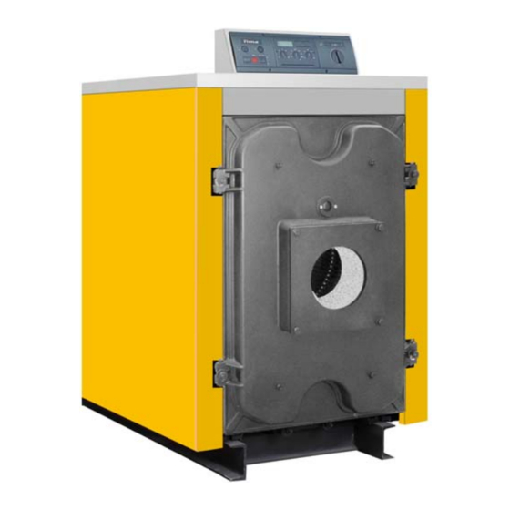
- Page 1 Oil / Gas Fired Boiler Cast iron Triple -Pass Design 378 kW to 930 kW...
-
Page 2: Table Of Contents
CONTENTS Page INTRODUCTION GUARANTEE TERMS GENERAL WARNINGS GENERAL CHARACTERISTICS OF OM SERIES BOILERS OM SERIES CAST IRON BOILER - TECNICAL DATA OM SERIES CAST IRON BOILER - DIMENSIONS BOILER ROOM SETTINGS AND BOILER PLATFORM DIMENSIONS PLUMBING INSTRUCTIONS A SAMPLE PLUMBING DIAGRAM FOR OM SERIES CAST IRON BOILERS THE MEANING OF THE SYMBOLS USED IN THE DIAGRAM DIAGRAM OF A SAMPLE SINGLE BOILER HEATING CIRCUIT WITH WATER HEATER WATER CIRCULATION PRINCIPAL... -
Page 3: General Warnings
GUARENTEE TERMS *In the terms of obeying the instructions,warnings, points in this manual and the standards in charge (EN norms and directives must be applied if mentioned standards are not in use.) cast body is under 5 (five) and other parts are under 2 (two) years guarantee. Our company is responsible for repairing or renewing if the following conditions are available. -
Page 4: General Characteristics Of Om Series Boilers
OM series boilers are delivered without burners. For suitable burner selection please get in touch with technicians. Suitable burners must be selected for taking high efficiency. If the boiler is stopped automatically because of over heating do not add cold water to the boiler for restarting. -
Page 5: Om Series Cast Iron Boiler - Tecnical Data . I
OM SERIES CAST IRON BOILER - TECNICAL DATA . I... - Page 6 OM SERIES CAST IRON BOILER - TECNICAL DATA . II...
-
Page 7: Om Series Cast Iron Boiler Dimensions
OM SERIES CAST IRON BOILER DIMENSIONS BOILER ROOM SETTINGS AND BOILER PLATFORM DIMENSIONS... -
Page 8: Plumbing Instructions
The measurements of the boiler room and the empty spaces must be arranged properly for future assembling repairing, re-assembling, burner connecting issues. * The concret platform must be in the mentioned dimensions. * Concrete platfrom must not be coated with slipper materials such as ceramics etc. * If sound izolaton will be made,first do the sound izolation than make the concrete for platform. -
Page 9: A Sample Plumbing Diagram For Om Series Cast Iron Boilers
A SAMPLE PLUMBING DIAGRAM FOR OM SERIES CAST IRON BOILERS This diagram is a sample diagram and does not include all of the safety requirements.Every system has its own characteristics and requirs a special project according to these specifications. The types and the quantities of heat cells in the dagram are examples. -
Page 10: Diagram Of A Sample Single Boiler Heating Circuit With Water Heater
DIAGRAM OF A SAMPLE SINGLE BOILER HEATING CIRCUIT WITH WATER HEATER OM SERIES CAST IRON BOILER... -
Page 11: Water Circulation Principal
= 20 K Boiler Capacity Type kCal/h Water Water Part Water Water Part Volume Resistance Volume resistance m³/h mbar m³/h mbar OM 06 325.000 377,9 21,67 16,25 OM 07 385.000 447,7 25,67 19,25 OM 08 435.000 505,8 29,00 21,75 OM 09 485.000... -
Page 12: Instructions About Flue
INSTRUCTIONS ABOUT FLUE Situations Can Make Problems In Flue: INSTRUCTIONS FOR CONNECTING THE FUEL TANK 1. Fuel Tank 6.Level Sign 2. Air Pipe 7. Heater 3. Filling Pipe 8. Fuel Suction Pipe 4. Unloading Valve Pipe 9. Off Valve 5. Unloading Valve 10. -
Page 13: Boiler Control Panels
BOILER CONTROL PANELS Standard Boiler Control Panel Single Level Standard Boiler Control Panel Dual Level... -
Page 14: Electrical Diagrams
ELECTRICAL DIAGRAMS Standard Boiler Control Panel (Single Level) - Electric Diagram Electric feedings is 220 V 50 Hz. Monophase Standard Boiler Control Panel (Dual Level) - Electric Diagram Electric feedings is 220 V 50 Hz. Monophase... -
Page 15: Cast Iron Sections With High Efficiency 3 Draught Design
CAST IRON SECTIONS WITH HIGH EFFICIENCY 3 DRAUGHT DESIGN 3rd Pass ( Smoke Channels) 2nd Pass 1st Pass 3 draught design forces the flue gas to circulate inside the body of the boiler three times before the chimney exit, transfering all usefull energy to the water inside the sections. The optimized combustion chamber combined with perfect heat insulation provides maximum fuel efficiency. - Page 16 LOADING AND UNLOADING BOILER WATER Unloading Water Of The Boiler Plumbing and all radiator valves must be opened if the boilers water will be unloaded. All the systems water can be unloaded by boilers drainage as if the boiler is in the bottom of the system. If some part of heating system is under the boiler room,unloading the water process can be made at a point at the bottom of the system.
-
Page 17: Om Serie Cast Iron Body -Boiler Cabin Parts List
OM SERIE CAST IRON BODY - BOILER CABIN PARTS LIST ! IMPORTANT *** Safety valve and expansion tank must be connected directly to the boiler and the place of use,without using any valve between... - Page 18 5,70 5,10 4,50 3,90 3,30 2,70 2,10 1,20 0,30...
-
Page 19: Important Instructions About Boiler Room
IMPORTANT INSTRUCTIONS ABOUT BOILER ROOM ! IMPORTANT There must not be any other equipments such as aspirator, air condition central etc. in the boiler rooms. These kind of equipments can make vacuum effect and defect boilers pull force. This can cause burner failures. -
Page 20: Boiler Room Airing
If natural airing system is used. ** Ventilating aring Type Needed for Force Airing ( cm² ) ( m³/h ) system is used Bottom Bottom ***Bottom value shows the clean air input up shows the OM 06 1.971 1.224 air output. OM 07 2.285 1.142 1.450 OM 08 2.546... -
Page 21: Failure First Control
Adjust the boiler temperature between 30 - 90 °C .If the burner is dual level, adjust the second level temperature 5- 10°C lower than the first one. This will turn second level light on. If the burner does not start follow the instructions written on the manual of the burner.If the burner does not start after applying the written operations in the manual,call the technical service of the burner. - Page 22 Situation and the leakproof of the sections and rope isolations controls. Working pressure test for burning adjustmenst with the flue gas measurement system if needed. Sensors and connection of the sensors test. Boiler burning room and possible soot layers on smoke channels are checks and cleanings. Connection and the leakproof of the boilers doors test.
-
Page 23: Cleaning The Boiler
CLEANING THE BOILER Before applying mentioned services to the boiler;electric must be cut off from the main switch,fuel valves must be closed, control panel and the burner must be protected for avoiding any possible damage. Smoke Channels Cleaning Because of the soot layer on heating surfaces, 100 °C increase on flue temperature brings out a % 5 decrease on efficiency. -
Page 24: Burner Connection Flange Sizes
BURNER CONNECTION FLANGE SIZES 45º Correct,proper burner must be chosen according to gas to gas side resistance valu- es of the boiler. Our company is not responsible for any possible problem if not certificated or out of standard burner is used with the boiler. M 12...
Need help?
Do you have a question about the OM 06 and is the answer not in the manual?
Questions and answers