Table of Contents
Advertisement
INSTALLATION AND OPERATION
MANUAL
FREESTANDING
AND INSERT
PELLET FIRED
STOVES
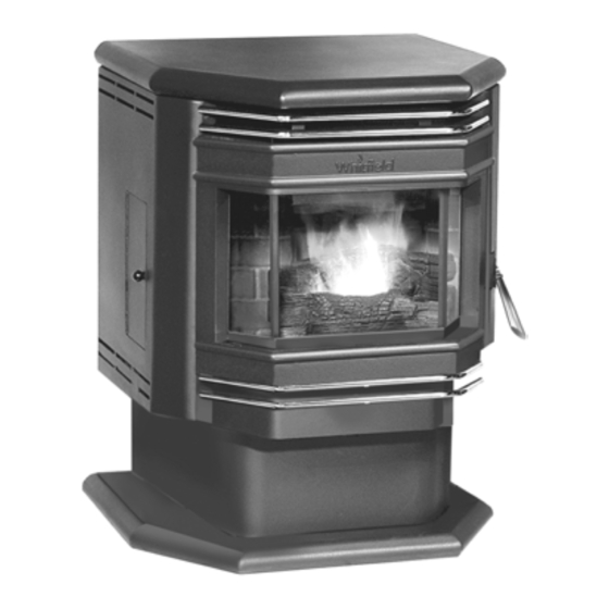
Freestanding Model
Advantage
Optima 2 FS *
Freestanding Model
RETAIN THESE
Advantage
Optima 3 FS *
INSTRUCTIONS
FOR FUTURE
Insert Model, Advantage Optima 3 INS not shown
REFERENCE
* Shown with Decorative Log Option
These appliances must be properly installed and operated in order to
prevent the possibility of a house fire. Please read this entire owner's
manual before installing and using your pellet stove. Failure to follow
these instructions could result in property damage, bodily injury or even
death. Contact your local building or fire officials to obtain a permit and
information on any installation requirements and inspection require-
ments in your area.
P/N 775097M, Rev. E, 12/03
Advertisement
Table of Contents

Related Manuals for Whitfield Advantage Optima 3 FS


Summary of Contents for Whitfield Advantage Optima 3 FS
-
Page 1: Installation And Operation
These appliances must be properly installed and operated in order to prevent the possibility of a house fire. Please read this entire owner's manual before installing and using your pellet stove. Failure to follow these instructions could result in property damage, bodily injury or even death. -
Page 2: Important Warnings
8. The stove will not operate using natural draft, nor without a power source for the blower and fuel feeding systems. -
Page 3: Table Of Contents
Sincerely, All of us at Lennox Hearth Products PACKAGING LIST The assembled pellet stove model Optima 2 FS, Optima 3 FS and Optima 3 INS are packaged with an accessory package, which contains the following: One - Installation and operation instructions manual. -
Page 4: Planning Your Installation
SELECTING A LOCATION The design of your home and where you place your stove will determine its value as a source of heat. This type of appliance depends primarily on air circulation (convection) to disperse its heat, and therefore, a cen- tral location is often best. - Page 5 FLOOR PROTECTION - Optima 2 FS This appliance requires noncombustible floor protec- tion. If the floor protection is to be stone, tile, brick, etc., it must be mortared or grouted to form a continuous non-combustible surface. If a chimney connector ex- tends horizontally over the floor, the protection must cover the floor under the connector and at least 2"...
- Page 6 PLANNING YOUR INSTALLATION FLOOR PROTECTION - Optima 3 FS The floor protector must meet or exceed the minimum thermal quirements as defined on this page (see Floor Protection/Hearth tension Using Alternate Material As Floor Pro- tector). If the floor pro- 6”/...
-
Page 7: Minimum Clearances To Combustibles
1" (see Safety / Listing Label) but for proper hopper lid operation in corner and parallel installations a 2" clearance is required. Rear Wall or Alcove – Optima 2 FS and Optima 3 FS Interior Vertical Flue inch / millimeter ♦4”... - Page 8 MASONRY AND FACTORY BUILT FIREPLACES The model Optima 3 INS is approved for installation into a solid fuel burning fireplace, either a masonry fireplace (built to UBC 37 or ULC S628 standards) or an approved factory-built / zero clearance fireplace (built to UL 127 or ULC S610 standards). See pages 20 and 21 for additional information on venting.
-
Page 9: Manufactured (Mobile) Home Installation
MANUFACTURED (MOBILE) HOME INSTALLATION Freestanding Models – Optima 2 FS and Optima 3 FS In addition to the standard installation instructions, the following instructions may be required by local, state or federal building codes: • Stove must be permanently bolted to the floor. -
Page 10: Installation
(located on each side of the in- sert back). Side View of Optima 2 FS & Optima 3 FS (Removing Back Pallet Bolts) Remove 1 bolt on each side of stove back Note: The pallet bolt at the front of appliance is located un- der the ash pan (this will require removing the ash pan. - Page 11 INSTALLING SURROUND ASSEMBLY - Optima 3 INS (to be done after venting system is installed) The surround kit (purchased separately) comes with a set of metal panels that enclose the fireplace opening when fitted together. There is also a trim assembly that frames the surround assembly to give it an attractive fin- ished appearance.
- Page 12 Optima 2 FS - The damper control handle is located on the right-hand side panel. Optima 3 FS - The damper control handle is located on the left-hand side panel. Optima 3 INS - The damper control handle is located on the left surround panel.
-
Page 13: Thermostat Installation
Make sure the wires are firmly con- nected to the thermostat. 5. Plug in the stove and you are ready to operate with your thermostat! IMPORTANT: IF THE WALL THERMOSTAT PROVIDED IS NOT USED, THE JUMPER IS REQUIRED FOR THE STOVE TO OPERATE. -
Page 14: Venting Requirements
Type of Pipe - This stove requires type “PL” (pellet vent pipe, sometimes referred to as “L-Vent pellet vent”), which conforms to UL standard 641. Connect the pellet vent pipe or the “tee”... -
Page 15: Vent Termination
Non-combustible shielding or guards may be required. Termination Cap: The termination of the outside chim- ney of the pellet stove shall be located in accordance with the following: A. Higher than 3’ (.92m) above any forced air inlet (air conditioner, etc.) located within 10’... -
Page 16: Installation Chart
INSTALLATION DETERMINING SIZE OF PIPE TO INSTALL To determine what diameter pipe to use in an installation (3” or 4”), first find the “equivalent pipe length” using the follow- ing guidelines, then plot this figure and the altitude on the chart. Fill out the installation chart, and calculate your total equivalent pipe length. - Page 17 High Tem- perature RTV sealer. 3. Push the stove (with pipe attached) towards wall. Pipe will go through the wall thimble. Do not position the back of the stove closer than 2” (51mm) from the wall. Back of Stove...
- Page 18 Standard Horizontal Installation Configurations Optima 3 FS Corner Through the Wall 3” (75 mm) Mini- mum clearance be- tween wall and pipe. If you vent to the furthest wall, the vent pipe must maintain a 3” clear- ance parallel to the other wall.
- Page 19 INSTALLATION Standard Vertical Installation Configurations Models: Optima 2 FS and Optima 3 FS These freestanding models may be connected to an existing flue or by installing listed type “PL” vent pipe. If a liner is run all the way to the top of the existing chim- ney, the existing flue should be sealed with a steel plate.
- Page 20 S t a n d a r d I n s t a l l a t i o n C o n f i g u r a t i o n s I n t o a n d E x i s t i n g F i r e p l a c e – M o d e l : Optima IMPORTANT- Make sure the chimney and firebox are clean and free of soot and ashes before installation begins.
- Page 21 INSTALLING OPTIMA 3 INS (CONTINUED) IMPORTANT- Make sure the chimney and firebox are clean and free of soot and ashes before installation begins. Fail- ure to do so may result in the transfer of soot into the room by way of the room air blower. Do not block opening at front of insert (below door).
-
Page 22: Care And Operation
Fault Mode – The control system automatically moni- tors the flame using a photoeye. If the stove runs out of pellets the control board automatically goes into a “fault” status. The control board will initiate the shut down cycle and safely shut down the stove leaving it in the “fault”... - Page 23 If your stove follows that described in number 2 above, simply press the ON / OFF button once to turn the stove off, this will initiate the cool down mode. The stove can be restarted at any time during the cool down mode by pressing the ON / OFF button once.
- Page 24 When first starting your pellet stove, it will be nec- essary to prime the auger tube. To prime the auger tube you need to first fill the hopper with pellets, and press the ON button on the control board.
-
Page 25: Manual Operation
2 minutes after flame is detected in the Ul- traGrate. A photoeye, monitors the existence of flame. After the start-up cycle your stove will be in the run mode. At this point the stove will operate in the heat output and blower settings selected. -
Page 26: Automatic Safety Features
Overheating: A high temperature disc (thermal switch) will automati- cally shut down the stove if it overheats. Allow up to 45 minutes cooling time before re-lighting. Keep enough convection air (from the room air blower) going through stove to keep it cooling properly, this will ensure long life of the stove. - Page 27 Clinkering is a function of the fuel, (not the stove), but adversely affects the performance of the stove by blocking off the air pas- sages in the grate. Even P.F.I. approved pellet fuel may tend to clinker.
-
Page 28: Routine Maintenance
ROUTINE MAINTENANCE * Inspect your stove or insert at minimum frequency stated until you establish a minimum frequency required for your installation (frequency will vary depending upon fuel BTU value / ash content, usage, and misc. installation variables). Unplug and Ensure Stove is Cold Before Performing Any Maintenance Work. Include routine mainte- nance with annual maintenance. - Page 29 ROUTINE MAINTENANCE 3. Release both ash pan latches and pull forward. Models Optima 2 FS and Optima 3 FS Model Optima 3 INS 4. Remove the ash pan. Place ashes into a non- combustible container. When finished, close the glass door and slide the ash pan back into the stove and close the ash pan door.
- Page 30 This area should be cleaned periodically to prevent excessive build-up, which may cause the stove to go into “fault” mode. (A) Cleaning Photoeye Filter Without Removing it: 1.
- Page 31 Clean-Out Tee ASH CLEAN-OUT PORTS Make sure stove is cold. Ash clean-out ports must be cleaned as part of routine maintenance. Accessing Clean-out Ports Optima 3 Series (Firebrick panels must be removed...
- Page 32 The door gasket does not need to be “tight” in all areas, since a small amount of leakage is not hazardous or detrimental to the performance of your stove. Door Rope Gasket (check seal at points indicated)
-
Page 33: Routine Maintenance
Do not apply oil to any part of the blower, doing so may cause damage. Opening Side Panels Optima 2 FS and Optima 3 FS Using a 11/32” nut driver remove the nut from the inside of the hopper on the side (see following picture). Reinstall... -
Page 34: Specifications
Flue Size Width, Overall Depth, Overall Depth, Overall w / 3” tee Height Floor to Rear Flue Center Facing back of unit, outside edge of left side to center of rear flue outlet center Floor to Rear Outside Air Inlet Located on center- line of pedestal back Facing back of Unit... - Page 35 SPECIFICATIONS - Optima 3 FS Flue Size 3” / 76mm Rear Width, Overall 25 7/8” Depth, Overall 24 7/8” Depth, Overall w / 3” tee 30 3/4” Height 31 3/8” Floor to Rear Flue Center 16 7/8” Facing Back of Unit,...
-
Page 36: Top View
Flue Size Width, Overall front (w/o surround) Width, Overall back (w/o surround) Depth, Overall (w/o surround) Height, rear (w/o surround) Height, front (w/o surround) Floor to Rear Flue Center Fireplace Face to Rear Flue Outlet Center (3” tee) Dimensions into Fireplace Minimum Height Minimum Width @ Front (extends back 1 ½”) -
Page 37: Definitions
AIR WASH To inhibit buildup of soot on the door glass, air is deliv- ered to the glass through an air wash system located in the doorframe surrounding the glass. AUGER It transfers the fuel down the burner tube into the burn grate. -
Page 38: Wiring Diagram
WIRING DIAGRAM PAGE 38... -
Page 39: Troubleshooting
Refill hopper. See (Pellets will not feed) this page. Allow stove to cool for 1 hour and re-light. If the stove has been operating at a medium to high burn rate and the room air blower has been turned down low then the fan should be turned up higher. If this problem persists (particularly at lower burn rates) then the high limit disc should be replaced by your authorized dealer. - Page 40 (High Temperature RTV). DO NOT use a standard household vacuum or “shop vac” as the filters will leak the fine particles of ash. Clean the stove with an ap- proved ash vacuum ONLY. Block excessive sunlight. Call authorized Lennox Hearth Products dealer if problem persists.
- Page 41 10% of line voltage (120v). 2.) Many nuisance ‘faults’ can be avoided by properly ‘breaking-in’ the stove. It is strongly recommended that the stove be run on the ‘high’ setting until 4 – 8 bags of fuel have been consumed. The auger / feed system will loosen up during this period and begin to feed at a slightly faster rate which may have an impact during the ‘start-up’...
-
Page 42: Replacement Parts List / Diagrams
16050205 Thermostat, Wall (wire not included) 12050815 Wiring Harness Stove Model Optima 2 FS Optima 3 FS & INS Optima 2 FS Optima 3 FS & INS Optima 2 FS Optima 2 FS Optima 3 FS & INS Optima 3 FS & INS Optima 2 FS Optima 3 FS &... - Page 43 Optima 2 FS Optima 3 FS & INS Stove Model Optima 2 FS Optima 3 FS Optima 3 INS Optima 2 FS & Optima 3 FS Optima 2 FS Optima 3 FS & INS Optima 2 FS & Optima 3 FS...
-
Page 44: Replacement Parts Diagrams
REPLACEMENT PARTS DIAGRAMS PAGE 44... - Page 45 PAGE 45...
- Page 46 PAGE 46...
- Page 47 REPLACEMENT PARTS DIAGRAMS PAGE 47...
-
Page 48: Optional Accessories
H0244 DLS-P H0464 DLS-AO3 H0432 HEK-AO3 H0416 ZCK-PI Optima 3 FS & INS Optima 2 FS Description Trim Kit, AO2 Gold Trim Kit, AO2 Nickel Trim Kit, AO3 Gold Trim Kit, AO3 Nickel Quick Disconnect Pipe Connector, 4” Touch-up Spray Paint Kit, Black Surround Kit, Small, 30 ½”... -
Page 49: Installation Tips
INSTALLATION TIPS PAGE 49... -
Page 50: Simple Operating Instructions
SIMPLE OPERATING INSTRUCTIONS LABEL PAGE 50... -
Page 51: Safety / Listing Label And Epa Label
SAFETY/LISTING LABEL – Model Optima 2 FS Note that your stove’s serial number is printed on the safety label, which is located near the inside of the hopper. Your stove’s serial number is preceded by a “WH-”(Example WH-0000000). PAGE 51... - Page 52 SAFETY/LISTING LABEL – Model Optima 3 FS and Optima 3 INS Note that your stove’s serial number is printed on the safety label, which is located near the inside of the hopper. Your stove’s serial number is preceded by a “WH-”(Example WH-0000000).
-
Page 53: Ownership Records
OWNERSHIP RECORDS Dealer’s Name: Dealer’s Address: City: Serial Number: Notes: SERVICE AND MAINTENANCE LOG Service Service Service Date Technician Description State: Date of Purchase: PAGE 53 Zip Code: Date Installed:... - Page 54 1110 West Taft Avenue Orange, CA 92865...
Need help?
Do you have a question about the Advantage Optima 3 FS and is the answer not in the manual?
Questions and answers