Table of Contents
Advertisement
Advertisement
Table of Contents

Related Manuals for CARLO GAVAZZI ISMG 315

Summary of Contents for CARLO GAVAZZI ISMG 315
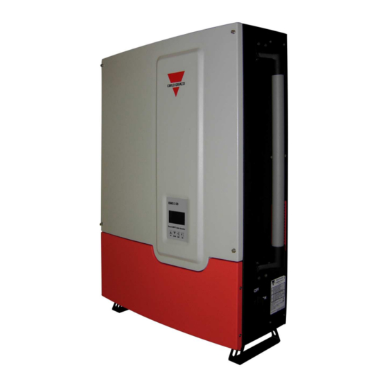
- Page 1 User Manual ISMG 315 / ISMG 320 Three-Phase Solar Inverter...
- Page 2 © 2010 Carlo Gavazzi Automation All rights reserved V 1.3 July 2010...
- Page 3 Safety KEEP THESE INSTRUCTIONS FOR FUTURE REFERENCE – This manual contains important instructions for Models ISMG 315 and ISMG 320 that shall be followed during installation and future maintenance of the ISMG inverter. Safety Precautions/Safety Notes Only trained skilled and qualified electrical personnel shall carry out e electrical installation, wiring, opening of the ISMG inverters.
-
Page 4: Safety Symbols
Safety Symbols To reduce the risk of injury and to ensure the continued safe operation of this product, the safety related information, contained in this manual are marked with the below listed signs. Warning, risk of electric shock These safety information prevent serious injuries or death to users and/or installers. -
Page 5: General Safety Precautions
The list does not contain all measures pertinent to the safe operation of the device. If special problems arise which are not described in sufficient detail for the purposes of the buyer, contact your local Carlo Gavazzi National Sales company or specialized dealer or technician. - Page 6 Safe Installation and Operation Installation of the device must be in accordance with the relevant national or local regulations. Correct grounding and short circuit protection must be provided to ensure operational safety. Read all instructions and caution remarks in the manual before installation. Switch off the circuit breakers before installation and wirings.
-
Page 7: Wiring The Inverter
Wiring the inverter WARNING! All electrical installation and the wiring methods shall be done in accordance with the relevant national or local electrical regulations and should follow the important safety instructions in this manual. WARNING! Make sure that you use suitable connecting cables for both the AC and DC wirings. -
Page 8: Connection Of The Ac Cable
Repair and Maintenance The inverter contains no user serviceable parts inside, except for the fans. Only CARLO GAVAZZI LOGISTICS SpA trained staff is authorized to repair the unit. Please return the equipment for further examination if the faults are not caused by fans. -
Page 9: Table Of Contents
Contents INTRODUCTION ENERAL PECIFICATIONS EATURES CCESSORIES INSTALLATION LACEMENT OUNTING IRING THE INVERTER 2.3.1 Connection of the AC cable..............27 2.3.2 Connection of the DC cable ...............29 2.3.3 Connection of the Communication cable .........32 IRING INVERTER IN PARALLEL OPERATION VERVIEW PERATION EATURES LCD D ISPLAY 3.3.1... - Page 10 RROR ESSAGES DESCRIPTION ROUBLESHOOTING TECHNICAL DOCUMENTATION UTLINE RAWING FFICIENCY RATING PERATION MPP E FFICIENCY WARRANTY INFORMATION...
-
Page 11: List Of Figures
List of Figures Fig1.1.1 Grid Connected Solar System Overview........... 4 Fig 2.1.1 Clearances required for ISMG3 inverter installation ......13 Fig 2.2.2 Inverter mounting bracket ..............15 Fig 2.2.3 Fasten the mounting bracket ............... 16 Fig 2.2.4 Hook the Inverter on the mounting bracket and then fasten the screw Fig 2.3.1 Turn the DC disconnect switch OFF............ - Page 12 Fig 4.3.1 Temperature de-rating curve of the ISMG320........75 Fig 4.3.2 DC Power curve of the independent PV string of the ISMG320..76 Fig 4.3.3 Output Power v.s. Grid voltage of the ISMG320 ........77 Fig 4.4.1 MPP Efficiency of the two PV strings in parallel ......... 78 Fig 4.4.2 MPP Efficiency of the two PV strings in individual......
-
Page 13: Introduction
Introduction General The Carlo Gavazzi ISMG3 product family is a series of grid-connected photovoltaic inverters which are designed to convert DC power generated by photovoltaic arrays to AC power that is delivered into the utility grid. The ISMG315 and ISMG320 are devices of the family with three (3) phases AC outputs for the European market. -
Page 14: Fig1.1.1 Grid Connected Solar System Overview
MPPT voltage setting. The ISMG3 inverter will be awakened again automatically when the input DC voltage rises above the minimum MPPT voltage point. We appreciated your choice of Carlo Gavazzi ISMG3 inverters for your power conversion devices in your solar power system. This document contains the information you need for the installation and settings of the ISMG3 inverters. -
Page 15: Specifications
Specifications Specifications for ISMG315 and ISMG320 Name-Part number ISMG 315 ISMG 320 Grid output (AC) Grid voltage, nominal 400VAC 3PH/N/PE Grid voltage, operating range 320 ~ 460VAC Grid frequency, nominal 50 Hz Grid frequency, operating 48~52.5 Hz (adjustable)* range 15,000 W... - Page 16 Maximum input current 2x21.6A (43.3 A) 2x28.9A (57.8 A) General Name-Part number ISMG 315 ISMG 320 Maximum efficiency 96.7 % 97.0 % CEC efficiency 95.5 % 96.0 % Night consumption < 1W Environmental Operating temperature range -25° ~ +60°C (-13° ~ +140°F) Storage temperature range -25°...
- Page 17 EN 61000-3-12(2004) Directive 2006/95/EC Low-Voltage Regulation EN 50178(1997), covered by IEC 62103(2003) VDE 0126-1-1(2006), RD 1663(2000) / RD 661 Network Monitoring (2007), DK 5940(2007) / Enel Connections Guide (2008), Section F RoHS Directive 2002/95/EC * Some factory settings can be re-configured with the approval of the local utility provider.
- Page 18 Adjustable voltage, Frequency and Reconnection Settings (1) DK5940 VDE0126-1-1 Setting Range Default Range Default Over-frequency (Hz) 50.05~50.95 50.25 50.05~50.15 50.15 Over-frequency disconnection time (cycle) Under-frequency (Hz) 49.05~49.95 49.75 47.55~49.95 47.55 Under-frequency disconnection time (cycle) Over-voltage (Vac) 235~270 235~260 Over-voltage disconnection time (cycle) Under-voltage (Vac) 188~225 188~225...
- Page 19 Adjustable voltage, Frequency and Reconnection Settings (2) RD1663 User Setting Range Default Range Default Over-frequency (Hz) 50.05~50.95 50.95 50.05~54.50 50.95 Over-frequency 1~250 disconnection time (cycle) Under-frequency (Hz) 48.05~49.95 48.05 45.50~49.95 49.05 Under-frequency 1~250 disconnection time (cycle) Over-voltage (Vac) 235~249 235~276 Over-voltage 1~150 disconnection time (cycle)
-
Page 20: Measurement Precision
Measurement precision Resolution Range Accuracy Display Measurement 0~900V 0.1V 0.3V ±2V Input voltage (VDC) 0~50000mA 100mA 15mA ±500mA Input Current (IDC) Grid voltage (VAC) 0~300V 0.1V 0.3V ±1V 0~60000mA 100mA 30mA ±500mA Grid current (IAC) 45~65Hz 0.01Hz 0.001Hz ±0.02Hz Grid frequency (Hz) 0~22000W ±50W Output power (W) -
Page 21: Features
Features High conversion efficiency Dual-MPP trackers (Can be connected in parallel) IP55 enclosure (Outdoor) Graphical display (Internal mini-datalogger) Three-phase balanced outputs Easy installation Smart self-diagnosis High power / small size ratio High reliability @ competitive price Conformity to VDE 0126-1-1 (ENS), RD1663/RD661 DK5940/Enel Connections Guide (2008), Section F Accessories Operation Manual (incl. -
Page 22: Installation
Installation Placement ∙ ISMG3 inverters, that must be vertically mounted, can be located indoor or outdoor according to protection degree of enclosure IP55. ∙ Leave at least 50 cm (19.7 inches) of free space above and 100 cm (39.4 inches) below the inverter when installed outdoor. Allow 20 cm (7.9 inches) between inverters when installing multiple inverters for better ventilation (see Fig 2.1.1). -
Page 23: Fig 2.1.1 Clearances Required For Ismg3 Inverter Installation
WARNING! Some parts of the cooling surface can reach temperatures over 70°C (158°F) when the inverter is in operation. Do not operate the inverter where it exposes to flammables, explosive atmospheres or close to combustibles or unknown materials that may result in fire/expolsion danger. -
Page 24: Mounting
Mounting The steps listed below describe how to mount the inverter on the wall: After taking out the inverter from the carton, the attached mounting bracket shall first be removed from the inverter by following the steps shown in Fig 2.2.1 below. -
Page 25: Fig 2.2.2 Inverter Mounting Bracket
Use the mount bracket (Fig 2.2.2) as a template to mark the location of the holes to be drilled in the wall. After drilling the holes, the mounting bracket is then held against the wall and fastened to the wall with anchors as shown in Fig 2.2.3. -
Page 26: Fig 2.2.3 Fasten The Mounting Bracket
Fig 2.2.3 Fasten the mounting bracket... - Page 27 Once the mounting bracket is fastened to the wall, the inverter can be mounted and fastened on the bracket. Hook the inverter on the mounting bracket flanges and slip down carefully to lock it in place. And then fasten the inverter to the mounting bracket as shown in Fig 2.2.4.
-
Page 29: Fig 2.2.4 Hook The Inverter On The Mounting Bracket And Then Fasten The Screw
Fig 2.2.4 Hook the Inverter on the mounting bracket and then fasten the screw After the inverter has been hooked correctly on the bracket and fastened to the mounting bracket, it is then possible to proceed with the wiring. -
Page 30: Wiring The Inverter
Wiring the inverter It is necessary to open the front lid of the wiring box before wiring the inverter. First, the DC disconnect switch must be turned OFF as shown in Fig 2.3.1. And then remove the two screws on the right hand side; open the red colour front lid of the wiring box as shown in the Fig 2.3.2 and Fig 2.3.3 below. -
Page 31: Fig 2.3.2 Loosen The Screws
Fig 2.3.2 Loosen the screws... -
Page 32: Fig 2.3.3 Open The Front Lid Of The Wiring Box
Fig 2.3.3 Open the front lid of the wiring box After the door is opened, it is then possible to remove the covers of the Threaded Conduit holes as shown in the Fig 2.3.4 for the DC and AC cables to be put through the threaded conduit holes in order to connect the inverter. -
Page 33: Fig 2.3.4 Removal Of The Covers For The Cable Through Holes
Fig 2.3.4 Removal of the covers for the cable through holes The following three sections describe the wiring for the AC, DC, and communication ports. The wiring shall carried out in the wiring box for the ISMG315 and ISMG320. There is a DC terminal block, two (2) RJ-45 connectors, and one (1) AC terminal block in the wiring box as shown in Figure 2.3.5. -
Page 34: Fig 2.3.5 Wiring Box Front View
Fig 2.3.5 Wiring box front view... - Page 35 WARNING! All electrical work shall carried out in accordance with the local and national electrical norms and should follow the important safety precautions contained in this manual. WARNING! Make sure that suitable connecting cables are used for both the AC and DC wirings.
-
Page 36: Fig 2.3.6 Utility Grid Configuration
Note: When connecting the ISMG3 inverter to the utility, the grid voltage must be compatible. Fig 2.3.6 Utility Grid Configuration... -
Page 37: Connection Of The Ac Cable
2.3.1 Connection of the AC cable Use the following procedures to wire the AC cables. Open the Distribution panel and switch off the circuit breaker used to connect the inverter to the grid. 2. Use 6 to 10 mm (#10 to #8 AWG), 90°C (194°F) copper wire for all AC wiring connections to the ISMG3 inverter. - Page 38 WARNING! Make sure that the circuit breaker to the mains utility is switched OFF before connecting the power cable from the breaker to the AC terminal block. WARNING! Each connection to an ISMG3 inverter must be installed with a dedicated circuit breaker in the mains utility service panel. The breaker must be sized in order to handle the rated maximum output voltage and current of an ISMG3 Inverter.
-
Page 39: Connection Of The Dc Cable
2.3.2 Connection of the DC cable The wiring box of the ISMG3 inverter is designed to support up to two (2) independent PV strings to be connected in the wiring box and then fed into the inverter. Fig 2.3.2.1 ISMG3 Inverter supports two (2) independent PV strings CAUTION! Overcurrent protection may be required depending on the type and ratings of the PV module configured in your system. -
Page 40: Fig 2.3.2.2 Pv Inverter Connections
There are two (2) terminals per PV string located inside the wiring box used for the DC cable connections. Up to two (2) independent PV strings are supported by the ISMG3 inverter. Therefore, there are four (4) terminals, two (2) of them are labeled with “+”... - Page 41 NOTE: The ISMG3 inverter with Dual-MPP tracker is designed to be applied to a variety of different configurations. In most cases it is recommended to link the two PV strings into a single hole to obtain the highest efficiency. Please consult with your installation servicer and see how to connect, as show in Fig 2.3.2.3.
-
Page 42: Connection Of The Communication Cable
2.3.3 Connection of the Communication cable The ISMG3 inverter supports two common data interface standards, RS-232 and RS-485 that will be used to communicate to a remote computer or terminal equipped with RS-232 or RS-485. Only one of the communication interfaces can work at a time. -
Page 43: Pins And Signals
RJ45-L TXD (RS232) RXD (RS232) Not used Top view Not used TX A (RS485) RX B (RS485) RJ45-R Factory reserved Factory reserved Top view TX A (RS485) RX B (RS485) Fig 2.3.3.2 RJ-45 Pins and Signals As shown in Fig 2.3.3.2, the RS-232 signal pins, TXD and RXD, are only on the RJ45-L. -
Page 44: Fig 2.3.3.3 Rs-232 Connection (Ismg-45S0918)
Fig 2.3.3.3 RS-232 connection (ISMG-45S0918) Fig 2.3.3.4 RS-485 connection... -
Page 45: Wiring Inverter In Parallel
Wiring inverter in parallel ISMG3 inverters can be connected in parallel when more power is required. In the parallel configuration, each inverter shall connect to its own PV array. It is not recommended to connect one PV array to more than one inverter. This may cause the inverter to work abnormally. -
Page 46: Operation
Operation Overview The control electronics will be active as soon as the DC (PV) voltage reaches “minimum MPPT” voltage point which is around 200VDC. The ISMG3 inverter is then powered up and will show “Illumination” on the LCD, complete the system initialization and wait for the DC voltage to reach the “PV start”... - Page 47 Checking: In this operation mode, the inverter checks all parameters on both AC and DC sides to ensure that connecting to the mains is safe. All conditions must be fulfilled and last for a certain period of time, then the system will enter the Grid/MPP mode.
- Page 48 it will go into the “System idle” mode and stop feeding the power to the grid for safety reasons. Normally this is a failure that cannot be removed by the user. This state requires maintainance staff operation in order to be reset and put the inverter back to normal operation.
-
Page 49: Operation Features
Operation Features 1. Anti-Islanding protection When an “islanding” condition is detected, for instance the utility grid falls or is disconnected by mean of the mains disconnector, the inverter will stop feeding the power on the AC output. An “island” is defined as a grid tied inverter maintaining operation and feeding power to a load that is isolated from the utility power source. -
Page 50: Lcd Display
LCD Display The ISMG3 inverter has a 128 x 64 graphic LCD Display with three (3) colours backlight, to display various information of the inverter such as the operating status/settings, input/output data, cumulated power, and error messages. furthermore, there is a keypad with 4 pushbuttons for users to select the information to be displayed on the LCD from one of the categories of “System Status”, “Energy Production”, and “Error Message”. -
Page 51: Lcd Backlight Indication
3.3.1 LCD Backlight Indication There are three (3) colours: white, green, and red, of LCD backlight. The colour will change according to the inverter operation status as shown in Figure3.3.1.1. The explanation of the status and the corresponding colours of the backlight are described in the following table. - Page 52 LCD backlight Operating status Description The inverter sets the initial values and Initialization detects all parameters. The low Sun irradiation can not start White Illumination the inverter. The inverter monitors all the system Checking parameters. The Inverter is feeding AC power to the Grid/MPP grid.
-
Page 53: Display Messages Flow
3.3.2 Display messages flow The display messages flow changes according to the procedure we are into. There are 3 main operation procedures: regular procedure, fault procedure or idle procedure. The regular procedure is when the system goes from power-on (illumination low), system check, and then Grid/MPPT mode without any fault condition detected. - Page 54 the LCD also displays the three-phase AC voltages, Frequency, and AC output power on the AC side. PVMate 20E PVMate 20E S/N: : : : 020010070001 S/N: : : : 020010070001 Ver. M00 & S00 Ver. M00 & S00 Std. DK5940 Std.
- Page 55 Checking: When the DC input voltage reaches the “PV start” voltage point, the inverter goes into the “Checking” Mode. In this operation mode, the inverter will check “Riso”, all parameters on both AC and DC sides, and then the AC relay to ensure that connecting to the mains is safe.
- Page 56 Grid/MPP: After the system has entered into the Grid/MPP (grid feeding) mode, the inverter will feed the AC power to the mains grid and show on the display, with green lolour backlight, the operating mode, the actual AC voltage, frequency, and. The other data such as the cumulated energy, the DC input power of each PV string, and the AC output power of each phase, can be displayed on the LCD by press the “DOWN”...
- Page 57 Mode: : : : Grid/MPP Mode: : : : Grid/MPP Mode: : : : Grid/MPP Vac: : : : 230/230/230V Vac: : : : 230/230/230V Vac: : : : 230/230/230V Fac: : : : 50.00Hz Fac: : : : 50.00Hz Fac:...
- Page 58 Derating: When power de-rating is detected, the “Derating” message will be displayed on the LCD as shown in the picture below. There are five possible situations that may cause output power derating. The ISMG detects only one derating situation at the time.
- Page 59 Warning: There are three possible warning messages that can be displayed on the Display when exespected situations occur in Grid/MPP mode: When the system has encountered a problem in accessing to the internal EEPROM memory device, the “EEPROM” warning message will be displayed The ISMG3 has encountered a communication error with the...
-
Page 60: System Fault
System Fault: When the system goes into the fault mode, it will shut off the output AC power, disconnect from the mains grid, and have the “System Fault” message displayed on the LCD with the backlight in red color as shown in the figure below. The fault(s) that cause the system going into the fault mode will be recorded. - Page 61 System Idle: When the ISMG3 inverter goes into the Idle mode, only service staff can clear this mode and reset the inverter. When in the idle mode, the ISMG3 inverter will shut off the output AC power, disconnect from the mains grid, and have the “System Idle”...
-
Page 62: Produced Power Graphs
3.3.3 Produced Power Graphs Press the “ESC” button to return to the main menu, then press the “Down” key until the “Graphic Method” is highlighted and then press the “OK” key to confirm the selection.The daily production graph will be displayed on LCD as shown in the figure below. - Page 63 If order to display the monthly chart, first press “ESC” key and then press the "DOWN" key to change to the monthly chart as shown below. On the upper right corner, it shows the present month. To change month press “OK” first and then press “DOWN”...
-
Page 64: Error Messages
3.3.4 Error Messages To review the recorded error messages, users shall select "Error Message", on the main screen, by pressing the “Down” or “Up” key from and then press the "OK" key to confirm. The LCD will then display the last error message recorded on the LCD with the date and time that the fault occurred. -
Page 65: Setting Operation
3.3.5 Setting Operation Some of the Inverter parameters can be re-configured from the built in panel. To chenge the paramaters select "Setting" from the main menu and then confirm by pressing the "OK", as shown below. The standard selection is password protected. The other settings such as the date, time, language, minimum start voltage, start-up time, buzzer ON/OFF, communication baud rate, and RS485 address, are not password protected. - Page 66 System Display System Display System Display System Display System Setting System Setting System Setting Standard: : : : DK5940 Standard: : : : DK5940 Standard: : : : DK5940 Graphic Method Graphic Method Graphic Method Graphic Method Baudrate: : : : Baudrate:...
-
Page 67: Auto Test (Only For Ismg315It And Ismgt320It)
Auto Test (Only for ISMG315IT and ISMGT320IT This Auto Test function is required according to the Italian Standard DK5940. With the Auto Test function, users may be able to verify the AC voltage and frequency (grid side) monitoring function. When the Auto Test function is running, the inverter will not provide AC power to the mains grid. -
Page 68: Auto Test Pc Software
3.4.1 Auto test PC Software The Auto Test software as an accessory provided with the inverter and should be installed in a computer which is connected to the inverter through the “RJ45-L port” (the RJ45 port on the left-hand side of the Inverter). Once the software is installed successfully, the .EXE file “ISMG315/320 Auto Test”... - Page 69 3.4.1.2 Communicated successfully Only one inverter at the time can be selected to run the Auto Test function even if more than one inverter is found. Users can choose the inverter by highlighting the serial number and then click the “Start Auto Test” button to run the Auto Test function, which will be performed in the order as shown in Figure 3.4.1.3 and described below.
- Page 70 voltage or frequency of the AC grid will be displayed on the PC screen. The maximum/minimum threshold values and the accepted trip time defined in DK5940 are as follows: Maximum AC voltage threshold: 270 V; < 80 ms b. Minimum AC voltage threshold: 188 V; < 160 ms Maximum AC frequency threshold: 50.25 Hz;...
-
Page 71: Fig 3.4.1.3 Auto-Test Process
Auto-test completed Fig 3.4.1.3 Auto-test process After all sub tests are completed, a popup window “All tests are finished” will appear on the PC screen and the “OK” key, on the PC screen, has to be pressed in order to stop the Auto Test software. -
Page 72: Use Self-Testing
3.4.2 Use Self-testing It is also possible to run the Auto Test function without a computer connected. From the main display menù, select “Setting” and then select “Auto Test” and press “OK” to perform the Auto Test function as shown below. (Please refer to Section 3.3.5) System Setting System Setting... - Page 73 CAUTION! If any one of these sub tests fails, the inverter will go into the “fault mode” and stop the test. The inverter will stay in “fault mode” and will not restart unless the test is re-run and it is Passed CAUTION! The only purpose of the Auto Test function is only to check the operation of the interface protection functionality of the inverter.
-
Page 74: Error Messages Description
AC power to the utility. Please contact Carlo Gavazzi local National Sales Company, your distributor or service representative if the same error message... - Page 75 Error Messages Table Error Message Description GridNA No AC voltage is detected on the utility grid side. VacH The AC voltage of utility grid is over the upper limit. VacL The AC voltage of utility grid is under the lower limit. FacH The AC frequency of the utility grid is over the upper limit.
- Page 76 Error Message Description Riso Low The insulation resistance between PV array and the ground is below the safe operating limit. VpvH The DC voltage of PV array is over the upper limit. IpvH Over current on the DC side. PpvH Over power on the DC side.
- Page 77 Error Message Description RCMU Fault Leakage current measurement device failure. I/P HCT Fault O/P HCT Fault Input/Output current sensor failure. HCT Fault Idc-inj. Fault DC injection current monitoring function failure. SPI Error Internal communication failure. EEPROM test failed. *warning message EEPROM Fault FanLock_A Cooling fan / fans stopped running.
-
Page 78: Troubleshooting
PV arrays following the connection procedures described in this manual. Try to identify and solve the problem based on the troubleshooting table below. If the problem cannot be identified and solved, please contact your local Carlo Gavazzi National Sales Company, distributor or service representative for assistance. - Page 79 Trouble Shooting Table Error Message Possible Causes Disposal Measures External communication Restart the inverter again; malfunction Inform professional service Comm. Error staff if failure does not restore Calibration parameters Inform professional service are deviated staff in order to check the CPUs diff.High calibration parameters Internal circuits...
- Page 80 Error Message Possible Causes Disposal Measures EEPROM's parameters Inform professional are unrecognized service staff to update EEPROM Fault the EEPROM's parameters FanLock_A Fan malfunction Inform professional FanLock_B staff to replace the fan DC or AC wires Check the DC and AC FastEarthCurrent insulation is damaged wire insulation...
- Page 81 Error Message Possible Causes Disposal Measures Internal circuit Restart the inverter again; Idc-inj. Fault malfunctions Inform professional staff if Offset Fault failure does not restore L2 and L3 cables are wired L2 and L3 wirings shall be L2, L3 Swap. reversed swapped Default settings are wrong...
- Page 82 and exhaust Ambient temperature is Ensure the ambient too high temperature is below 60°C Error Message Possible Causes Disposal Measures AC voltage or Wait until the grid is back to frequency exceeds stable condition VacH VacL the default settings FacH Mains voltage or Request the utility supplier to FacL...
-
Page 83: Technical Documentation
Technical Documentation Outline Drawing Fig 4.1.1 Outline Drawing of ISMG3... -
Page 84: Efficiency
Efficiency The efficiency of the ISMG315/320 is shown in Figure 4.2.1 and Figure 4.2.2 below. Fig 4.2.1 Efficiency of the ISMG320 = 96.0% Fig 4.2.2 Efficiency of the ISMG315 = 95.5%... -
Page 85: De-Rating Operation
De-rating Operation Here below are described the different situations in which the Inverter will limit the output power in order ensure the system operates in a safe condition. Temperature The ISMG3 inverter monitors the heat sink temperature. If the temperature exceeds 70°C (ambient temperature is around 45°C), the the output power will be reduced until the temperature falls under the critical value. -
Page 86: Fig 4.3.2 Dc Power Curve Of The Independent Pv String Of The Ismg320
Input DC current excess When the input current from the PV strings is about to exceed the maximum value, the ISMG3 inverter will limit it to the safe operating value in order to prevent damages to the inverter. If this situation occurs frequently, it is necessary to check whether the PV arrays are properly configured according to the Inverter DC current limit. -
Page 87: Fig 4.3.3 Output Power V.s. Grid Voltage Of The Ismg320
Output AC current The maximum current that the ISMG3 inverter feeds to the grid is limited according to the specifications listed in Section 1.2. Fig 4.3.3 Output Power v.s. Grid voltage of the ISMG320... -
Page 88: Mpp Efficiency
MPP Efficiency The ISMG315/320 supports up two (2) PV strings that can be either connected in parallel, feeding into a single MPP tracker, or connected individually to each MPP tracker. The efficiencies of the 2 configurations: two(2) PV strings connected in parallel and connected individually are shown in Figure 4.4.1 and Figure 4.4.2 respectively. - Page 89 WARNING! PV arrays are always energized when exposed to light therefore hazardous voltage is still present on the terminal blocks and the PV string fuse holders even the DC disconnect switch is switched OFF. Please cover the PV arrays with opaque (dark) materials during the inverter removal.
-
Page 90: Warranty Information
Warranty information Warranty Period A period of 5 years is warranted from the date of your purchase of the ISMG3 series Products. Additional 5 years warranty: warranty extension up to 10years can be purchased separately within the term specified in the “warranty terms certificate” from purchase date of the unit Warranty Terms The warranty terms of the ISMG3xx Inverters are specified in the “Warranty terms... - Page 91 Your Notes :...
Need help?
Do you have a question about the ISMG 315 and is the answer not in the manual?
Questions and answers