
Related Manuals for DeWalt DW713-XE


Summary of Contents for DeWalt DW713-XE
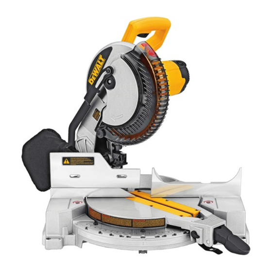
- Page 1 Questions? See us on the World Wide Web at www.dewalt.com INSTRUCTION MANUAL DW713-XE 254 mm (10") COMPOUND MITER SAW...
-
Page 3: Table Of Contents
TABLE OF CONTENTS DOUBLE INSULATION ............................2 CROSSCUTS ..............................8 BEVEL CUTS..............................8 SAFETY INSTRUCTIONS FOR ALL TOOLS ......... …………………………………………2 QUALITY OF CUT ............................... 8 ADDITIONAL SAFETY RULES ........……………………………………………………….2 BODY AND HAND POSITION ..........................8 ELECTRICAL SAFETY ..........…………………………………………………………4 CLAMPING THE WORKPIECE ........................ -
Page 4: Double Insulation
• MAINTAIN TOOLS WITH CARE. Keep tools sharp and clean for best and safest performance. Follow Definitions: Safety Guidelines instructions for lubricating and changing accessories. Poorly maintained tools and machines can further damage the tool or machine and/or cause injury. The definitions below describe the level of severity for each signal word. - Page 5 • BE SURE all blade and blade clamps are clean, recessed sides of blade clamps are against blade and arbor • ADDITIONAL INFORMATION regarding the safe and proper operation of power tools (i.e. a safety video) screw is tightened securely. Loose or improper blade clamping may result in damage to the saw and possible is available from the Power Tool Institute, 1300 Sumner Avenue, Cleveland, OH 44115-2851 (www.
-
Page 6: Electrical Safety
Electrical Safety The electric motor has been designed for one voltage only. Always check that the power supply corresponds to the voltage on the rating plate. 230 V AC means your tool will operate on alternating current. As little as 10% lower voltage can cause loss of power and can result in overheating. -
Page 7: Accessories
FIG. 2 OPERATING HANDLE FIG. 3 TRIGGER HEAD LOCK SWITCH LEVER CARRYING SPINDLE LOCK HANDLE BUTTON GUARD MOTOR HOUSING LEFT-SIDE FENCE MOTOR END CAP CLAMPING KNOB RIGHT SIDE FENCE TABLE LEFT-SIDE FENCE DUST SPOUT LOCK DOWN PIN LEFT-SIDE FENCE MITER LOCK CLAMPING KNOB LEVER BEVEL CLAMP KNOB... -
Page 8: Bench Mounting
Bench Mounting 5. Keeping the button depressed, use the other hand and the wrench FIG. 6 Transporting the Saw provided to loosen the blade screw. (Turn clockwise, left-hand Holes are provided in all four feet to facilitate bench mounting, as shown WARNING: To reduce the risk threads) in Figure 2. -
Page 9: Bevel Pointer
FIG. 7 BEVEL POINTER FIG. 10A If the bevel pointer does not indicate zero, loosen the screw that holds it in place and move the pointer as necessary. SUGGESTION: For accuracy, set the top edge so that it aligns with zero. BEVEL HOUSING BEVEL STOP... -
Page 10: Crosscuts
If a delay or “skipping” occurs, turn the saw on and off 4 or 5 times. If FIG. 12 FIG. 15 the condition persists, have the tool serviced by an authorized D WALT service center. Always be sure the blade has stopped before removing it from the kerf. STOP The brake is not a substitute for guards or for ensuring your own safety SCREW... -
Page 11: Clamping The Workpiece
Keep both feet firmly on the floor and maintain proper balance. As you FIG. 16A FIG. 16 move the miter arm left and right, follow it and stand slightly to the side of the saw blade. Sight through the guard louvers when following a pencil line. -
Page 12: Cutting Compound Miters
FIG. 17 3. To set the additional 1/4°, squeeze the miter arm lock and carefully FIG. 18 position the wood with the broad flat side on the table and the narrow move the arm to the RIGHT until the 1/4 degree vernier mark aligns edge against the fence. -
Page 13: Cutting Base Molding
When mitering to the right side of a base molding wider than 88.9 mm FIG. 26 FIG. 23 (3.5") standing vertically against the fence as in Figure 25, the saw can only cut through the board up to 1 inch from the end of the board. Trying to cut more than an inch will cause the saw’s gear case to interfere with the workpiece. -
Page 14: Cutting Crown Molding
OUTSIDE CORNER: FIG. 29 FIG. 31 Left side 1. Position molding with bottom of the molding against the fence 2. Save right side of cut Right side 1. Position molding with top of molding against the fence 2. Save right side of cut FENCE CUTTING CROWN MOLDING Your miter saw is better suited to the task of cutting crown molding than... -
Page 15: Special Cuts
Right side FENCE Guarantee FIG. 33 1. Miter right at 45° Applicable to hand held Power Tools, Lasers and Nailers. 2. Save left side of cut Three Year Limited Warranty Special Cuts WALT will repair, without charge, any defects due to faulty materials or NEVER MAKE ANY CUT UNLESS THE MATERIAL IS SECURED ON THE workmanship for three years from the date of purchase. -
Page 16: Troubleshooting Guide
TROUBLESHOOTING GUIDE BE SURE TO FOLLOW SAFETY RULES AND INSTRUCTIONS TROUBLE! WHAT’S WRONG? WHAT TO DO Saw will not start 1. Saw not plugged in 1. Plug in saw 2. Fuse blown or circuit breaker tripped 2. Replace fuse or reset circuit breaker 3. -
Page 17: Compound Miter Cut Reference Chart
TABLE 1: COMPOUND MITER CUT (POSITION WOOD WITH BROAD FLAT SIDE ON THE TABLE AND THE NARROW EDGE AGAINST THE FENCE) SET THIS MITER ANGLE ANGLE OF ON SAW SIDE OF BOX (ANGLE A) BEVEL DEGREE SETTING SET THIS BEVEL ANGLE ON SAW... - Page 20 WALT Industrial Tool Co., 701 East Joppa Road, Baltimore, MD 21286 • 20 Fletcher Road, Mooroolbark, VIC 3138 Australia (NOV07) Form No.648398-00 DW713-XE Copyright © 2007 D WALT The following are trademarks for one or more D WALT power tools: the yellow and black color scheme; the “D” shaped air intake grill; the array of pyramids on the handgrip; the kit box configuration; and the array of lozenge-shaped...
Need help?
Do you have a question about the DW713-XE and is the answer not in the manual?
Questions and answers