Table of Contents
Advertisement
Quick Links
SPECIAL NOTICE
This product is now licensed to Anodyne Electronics Manufacturing (AEM) from Northern
Airborne Technology (NAT). AEM is responsible for all matters related to this product, including
sales, support and repair services.
Please note the transition to convert product manuals and supporting documentation is an
ongoing process and is being addressed on an 'as needed' basis.
All references to NAT product part numbers (and associated images) are equivalent to AEM
product part numbers.
Contact info:
Anodyne Electronics Manufacturing Corp.
#15-1925 Kirschner Road
Kelowna B.C. Canada
V1Y 4N7
Email:
support@aem-corp.com
Toll Free: 1-888-763-1088
Phone: 1-250-763-1088
Fax: 1-250-763-1089
www.aem-corp.com
Advertisement
Table of Contents

Summary of Contents for AEM SM10
- Page 1 SPECIAL NOTICE This product is now licensed to Anodyne Electronics Manufacturing (AEM) from Northern Airborne Technology (NAT). AEM is responsible for all matters related to this product, including sales, support and repair services. Please note the transition to convert product manuals and supporting documentation is an ongoing process and is being addressed on an ‘as needed’...
- Page 2 REV 5.00 April 14, 2012 Anodyne Electronics Manufacturing Corp. 15-1925 Kirschner Road Kelowna, BC, Canada. V1Y 4N7 Telephone (250) 763-1088 Facsimile (250) 763-1089 Website: www.aem-corp.com © 2012 Anodyne Electronics Manufacturing Corp. (AEM), All Rights Reserved CONFIDENTIAL AND PROPRIETARY TO ANODYNE ELECTRONICS MANUFACTURING CORP.
- Page 3 COPYRIGHT STATEMENT © 2012 Anodyne Electronics Manufacturing Corp. (AEM), All Rights Reserved This publication is the property of AEM and is protected by Canadian copyright laws. No part of this document may be reproduced or transmitted in any form or by any means including electronic, mechanical, photocopying, recording, or otherwise, without the prior written permission of AEM.
- Page 4 AA31 ICS Mode Controller SM10 Installation and Operation Manual Prepared By: Checked By: Approved By: Tom Betzelt Tony Pearson Loen Clement Product Support Designer Designer Manager Apr 14, 2012 May 24/12 May 28, 2012 The status of this installation and operation manual is controlled by issue shown on the title page. The status of each section is controlled by revision shown in the footer of each page.
-
Page 5: Table Of Contents
AA31 ICS Mode Controller SM10 Installation and Operation Manual Table of Contents Section Title Page Description Introduction Purpose of Equipment Features Specifications 1.4.1 Electrical Specifications 1.4.2 Physical Specifications 1.4.3 Environmental Specifications Unit Nomenclature Installation Introduction Unpacking and Inspection 2.2.1 Warranty Installation Procedures 2.3.1... -
Page 6: Description
The AA31 can provide ICS switching for three or four AEM Audio Controllers, or other AEM products incorporating an ICS TIE LINE. The AA31 also has provisions for driving external annunciators and interfacing for ICS Calling. -
Page 7: Specifications
AA31 ICS Mode Controller SM10 Installation and Operation Manual Specifications 1.4.1 Electrical Specifications Input Power +28 Vdc Power Requirements Nominal 155 mA max @ +27.5 Vdc Lighting 80 mA max @ +27.5 Vdc Annunciators REAR CALL (left) Amber (dimming) REAR CALL (right) -
Page 8: Environmental Specifications
6 g for 11 ms Qualification DO-160C Env. Cat. B4-BA[MN]XXXXXXXXXXXXXXXX Unit Nomenclature Other variants are available; please contact AEM for further information. AA31-001 Mode selector for organizing multiple ICS circuits Visual LED annunciation of mode status External annunciation – 100mA max @ 28 Vdc... -
Page 9: Installation
Verify that all items are present before proceeding and report any shortage immediately to your supplier. 2.2.1 Warranty All Anodyne Electronics Manufacturing Corp. (AEM) products are warranted for 2 years. See the website www.aem-corp.com/warranty for complete details. Installation Procedures 2.3.1 Warnings Do not bundle any lines from this unit with transmitter coax lines. -
Page 10: Notes
AA31 ICS Mode Controller SM10 Installation and Operation Manual Allow 3 inches from the end of the wire to the shield termination to allow the hood to be easily installed. Note that the hood is a ‘clamshell’ hood, and is installed after the wiring is complete. -
Page 11: Continued Airworthiness
AA31 ICS Mode Controller SM10 Installation and Operation Manual 2.3.6.2 Power On Checks Power up the audio system with the AA31 installed. Verify that the ISO (amber) and COMMON (green) LEDs light as the ICS Function Knob is rotated from the ALL COMMON position to the isolated positions. -
Page 12: Installation Drawings
AA31 ICS Mode Controller SM10 Installation and Operation Manual Installation Drawings DRAWING REV. DESCRIPTION TYPE AA31-001 AA31\001\403-0 1.01 ICS Mode Controller Interconnect AA31\001\405-0 1.01 ICS Mode Controller Connector Map AA31\001\905-0 1.10 ICS Mode Controller (Sheet 1 of 2) Faceplate AA31\001\922-0 1.10... - Page 19 2.00 13-Dec-11 RAS#33 - CHANGED TO AEM LOGO, UPDATED HOLE SCHEDULE. PILOT ISO PILOT ISO PILOT ISO REAR ISO REAR ISO REAR ISO REAR REAR REAR REAR REAR REAR ALL ISO ALL ISO ALL ISO ALL COMMON ALL COMMON ALL COMMON...
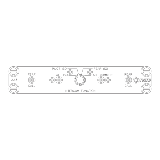
- Page 20 DESCR DATE REVBY 2.00 RAS#33 - UPDATED TO AEM FORMAT. 04-Jan-12 4.90 124.5 2.46 62.5 EST. PRODUCT LABEL 0.95±0.02 24.1±0.5 PILOT ISO REAR ISO REAR REAR ALL ISO ALL COMMON AA31 CALL CALL INTERCOM FUNCTION 5.75 146.1 3.95±0.05 100.3±1.3 UNLESS OTHERWISE SPECIFIED: 15-1925 KIRSCHNER RD.
-
Page 21: Operation
AA31 ICS Mode Controller SM10 Installation and Operation Manual Section 3.0 Operation Introduction Information in this section consists of the functional and operational procedures for the AA31 ICS Mode Controller. General The AA31 ICS Mode Controller provides a convenient, centralized method of organizing the aircraft audio system into multiple intercom circuits for independent or common operation. -
Page 22: Annunciators
AA31 ICS Mode Controller SM10 Installation and Operation Manual Selecting REAR ISO isolates the Pilot and Co-pilot from the Rear position(s). The ICS tie lines of the Pilot and Co-pilot Audio Controllers are connected together, but there is no connection between the Front (Pilot or Co-pilot) and Rear Audio Controller(s).
Need help?
Do you have a question about the SM10 and is the answer not in the manual?
Questions and answers