Advertisement
Quick Links
Installation and Assembly Instructions
The photovoltaic module produces electricity when exposed to the sun or
other light sources. For your safety and the safety of others, please read
the entire Installation and Assembly Instruction manual carefully prior to
installation. Please carefully read the following installation and safety
instructions. Non-compliance with these instructions may void the module
warranty.
1. Company Introduction
ET Solar Group is a vertically integrated solar energy equipment manufacturer and
turnkey solutions provider. With local sales and marketing subsidiaries and offices
throughout Asia, Europe, and North America, we provide high quality photovoltaic
modules, world leading solar tracking systems and smart turnkey solutions to our
customers in more than 50 countries and areas. Our products have been delivering strong
operating performance in a large number of residential and utility scaled solar PV
projects around the world.
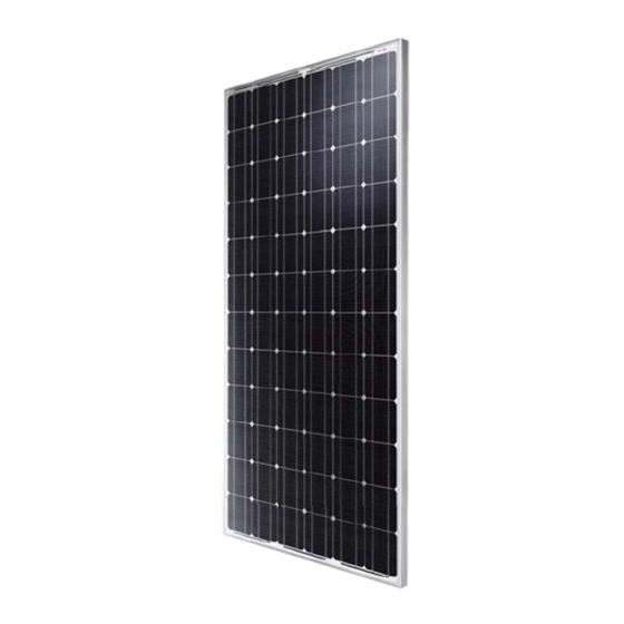
2. Structure of module
ET modules are made by layering low-iron-tempered glass, an EVA sticky membrane,
high conversion-efficient solar cells and a behind-the-membrane multi-layer backsheet.
These elements are laminated into a plate by being heated in a vacuum. After installing
the aluminum alloy frame and wiring compartment, a module is born (see Fig. 1)
.
for Solar Modules
WARNING!
1
Advertisement

Related Manuals for ET Solar ETM53670


Summary of Contents for ET Solar ETM53670
- Page 1 Non-compliance with these instructions may void the module warranty. 1. Company Introduction ET Solar Group is a vertically integrated solar energy equipment manufacturer and turnkey solutions provider. With local sales and marketing subsidiaries and offices throughout Asia, Europe, and North America, we provide high quality photovoltaic modules, world leading solar tracking systems and smart turnkey solutions to our customers in more than 50 countries and areas.
- Page 2 Fig.1: Front and back sides of ET-M572170 module 3. Installation of modules WARNING! Do not attempt to clean a module with a broken glass cover or a perforated backsheet. Such a module can present a serious shock hazard. 3.1 Installation When installing the modules, the face of the units should be placed where they are highly exposed to the sun.
- Page 3 The recommended standoff height is 5 in. (127mm), if other mounting means are employed this may affect the UL Listing. The specific angle depends on the sunlight condition, local climate and the actual application requirements. The appropriate angle of evaluation has a very important relationship to the output power of the modules and the cost of the construction.
- Page 4 located on the aluminum alloy frame, are provided for ease of installation. They are designed to be used with metric M6×1(Torque 12 Lb-in) stainless steel screws. Mounting with Bolts • The module must be attached and supported by at least four bolts through the indicated mounting holes.
- Page 5 WARNING! The Fire Rating of this module series is Class “C”. Grounding: All permanently mounted modules have to be provided with appropriate grounding. The grounding lug should be suitable for outdoor use with aluminum. The grounding method of the frame of arrays shall comply with the NEC, article 250 and also meet UL 1703 standard.
- Page 6 The junction box should be fixed on the top end of the module during assembly so as to prevent the seepage of rain. ET Solar provides a wiring type box. When the integrated J-box is adopted, no tool is necessary for wiring. Just connect the modules in series according to “+” or “-”. You can complete complex series and parallel connection easily and quickly using different electric connectors provided by your supplier.
- Page 7 Wiring must only be completed by a qualified engineer with suitable tools. The specification of wire for the electric coupler that ET Solar provided is 1 x 4.0mm Equivalent wire should be used if the user prefers to use his own wire. When the module’s rated current is lower, 12AWG wire is recommended for use, and the strength...
- Page 8 conditions (irradiance of 100 mW/cm , AM1.5 spectrum, and a cell temperature of 25 F)). Under normal conditions, a photovoltaic module is likely to experience conditions that produce more current and/or voltage than reported at standard test conditions. Accordingly, the values of Isc and Voc marked on this module should be multiplied by a factor of 1.25 when determining component voltage ratings, conductor capacities, fuse sizes, and size of controls connected to the PV output.
- Page 9 For the best impedance matching and the best tracking of maximum power output, please refer to other relevant documents regarding these issues. Electrical ratings of ET Solar modules are as follows. The detailed specs should refer to module datasheet.
- Page 10 Therefore, a lower environmental temperature is most appropriate for the module. 5. Operation and Maintenance ET Solar module users should rinse the array seasonally or as needed in dry, dirty areas to improve the performance of their solar electrical systems. Heavily soiled modules will have a decrease in performance due to reduced light on the photovoltaic cells.
- Page 11 No responsibility is assumed by ET Solar for any infringement of patents or other rights of third parties, which may result from use of the PV product. No license is granted by implication or otherwise under any patent or patent rights.
- Page 12 Please consult your dealer or the manufacturer concerning the warranty of your modules. 2010 © ET Solar Group.
Need help?
Do you have a question about the ETM53670 and is the answer not in the manual?
Questions and answers