
Subscribe to Our Youtube Channel
Related Manuals for Alarm SAF CPS2


Summary of Contents for Alarm SAF CPS2
- Page 1 VOLTS 6 12 24 J2 C C CPS200/400 ALARMSAF CPS 800/1000 Model CPS2 - CPS1000 Power Supply / Battery Charger Operating and Installation Instructions 52-209 Rev B.02...
-
Page 2: Warnings And Notices
CPS2-CPS1000 Installation Instructions 5/24/13 I. Warnings and Notices WARNING - To reduce the risk of fire or electric shock, do not expose this product to rain or moisture WARNING - This installation and all servicing should be made by qualified... -
Page 3: Table Of Contents
CPS2-CPS1000 Installation Instructions 5/24/13 Table of Contents Section Page I. Warnings and Notices 1 Introduction 2 Applicable Standards / Documents 3 System Overview 3.1 Electrical Ratings and Specifications 3.2 Terminal Descriptions and Electrical Ratings 3.3 AC Input Connection 3.4 Battery Terminals 3.5 DC1 Output Terminals... -
Page 4: Introduction
CPS2-CPS1000 Installation Instructions 5/24/13 Section 1 Introduction The CPS line of power supplies provides a field selectable 12VDC or 24VDC at 2.5A to 10A (depending on model) using buck topology switching technology. Features: Field-selectable output voltage of 12V or 24VDC - Specific models also provide a 6V setting... -
Page 5: Applicable Standards / Documents
CPS2-CPS1000 Installation Instructions 5/24/13 Section 2 Applicable Standards / Documents NFPA Standards NFPA 72 National Fire Alarm Code NFPA 70 National Electrical Code NFPA 731 Standard for the Installation of Electronic Premises Security Systems UL and Canadian Standards (Applies to model numbers ending in “-UL/CSA” only) UL 294 Access Control System Units CSA C22.2... -
Page 6: System Overview
CPS2-CPS1000 Installation Instructions 5/24/13 Section 3 System Overview 3.1 Electrical Ratings and Specifications Manufactured By AlarmSaf Tel: 800 987 1050 65A Industrial Way Tel: 978 658 6717 Wilmington, MA 01887 Fax: 978 658 8638 www.alarmsaf.com Model Numbers and Electrical Ratings... -
Page 7: Terminal Descriptions And Electrical Ratings
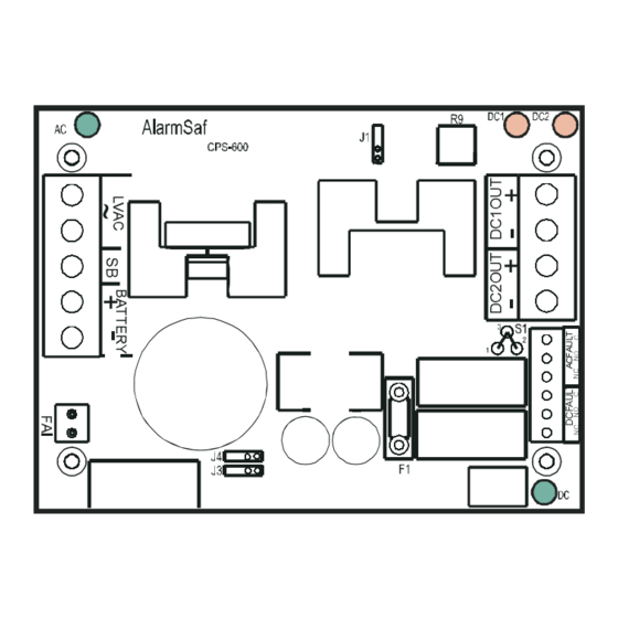
CPS2-CPS1000 Installation Instructions 5/24/13 3.2 CPS Board Terminal Descriptions and Electrical Ratings Terminal / Connector Description Rating TB1 - Low Voltage AC Input and Battery Output LVAC Low voltage AC input 28.2VAC - See Table 3.1 for Ratings LVAC Special Battery Terminal... -
Page 8: Ac Input Connection
CPS2-CPS1000 Installation Instructions 5/24/13 3.3 AC Input Connection 3.3.1 Board-Level Supplies Board-level units are connected to an appropriate low-voltage AC supply voltage of a sufficient VA rating (See Table 3.1). The connection is made on TB1 at the terminals labeled “LVAC.”... -
Page 9: Dc2 Output Terminals
CPS2-CPS1000 Installation Instructions 5/24/13 3.6 DC2 Output Terminals The DC2 output terminals provide a controlled output of either 12VDC or 24VDC. Control is provided through the FAI input. The operation of the DC2 output is set by jumper S1. See Appendix A for more information on using the FAI Input and DC2 output. -
Page 10: Installation
CPS2-CPS1000 Installation Instructions 5/24/13 Section 4 Installation 4.1 Mounting The CPS line is available in either board-level or cabinet level versions. 4.1.1 Mounting a Cabinet-Level Supply If the CPS is provided in a wall mount enclosure, use #8 hardware minimum in four locations. -
Page 11: Wiring
CPS2-CPS1000 Installation Instructions 5/24/13 4.2 Wiring 4.2.1 Wire Routing All wiring must be installed in accordance with NFPA70, NFPA72, and all local code requirements. Power Limited wiring requires that power limited and non-power limited wiring remain physically separated. Any power limited circuit entering the enclosure must remain at least one quarter inch ( ”) away from any non-power limited circuit wiring. -
Page 12: Operating The Cps
CPS2-CPS1000 Installation Instructions 5/24/13 Section 5 Operating the CPS 5.1 Setting the Jumpers Before powering a system containing a CPS, the jumpers should be set for proper operation. Be sure to reference the proper section of the manual (5.1.1 or 5.1.2) for the model of CPS you are using. -
Page 13: Visual Indicators
CPS2-CPS1000 Installation Instructions 5/24/13 5.1.2 Units WITHOUT Fault Relay Output Jumper 6V Output 12V Output* 24V Output *Factory default Closed Open Open Open 5.1.2.1 Output Voltage Setting (J1 & J2) J1 and J2 control the output voltage setting of the CPS. CPS models without Fault Relays may be set for 12VDC, or 24VDC output. -
Page 14: Troubleshooting
CPS2-CPS1000 Installation Instructions 5/24/13 5.3 Troubleshooting Condition Possible Cause Solution Incorrect jumper settings Verify proper jumper settings Verify that output current is less than Excessive loading on output rated current The output voltage of the CPS is AC trouble Verify presence of AC voltage... -
Page 15: Specifications
CPS2-CPS1000 Installation Instructions 5/24/13 Section 6 Specifications 6.1 Electrical Specifications 6.1.1 Input Voltage See Section 3.1 6.1.2 Input Power See Section 3.1 6.1.3 Output Voltage 12 or 24VDC Nominal - See Section 5.1 6.1.4 Output Current See Section 3.1 6.1.5 Maximum Battery Charger Capacity See Section 3.1... -
Page 16: Using The Fai Input And Dc2 Output
CPS2-CPS1000 Installation Instructions 5/24/13 Appendix A Using the FAI Input and DC2 Output Some models of CPS have an FAI input and a DC2 output, which is controlled by the FAI input. The FAI input may be activated by either a Normally Open or a Normally Closed contact, and the DC2 output can operate either as Fail-Safe of Fail-Secure by setting the S1 jumper appropriately (See Section 5.1). -
Page 17: Using The Sb (Special Battery) Terminal
CPS2-CPS1000 Installation Instructions 5/24/13 Appendix B Using the SB (Special Battery) Terminal The SB Terminal allows the use of a single battery set in dual voltage systems utilizing multiple power supplies. A 24V battery set is connected to the 24V power supply as normal, then also connected to the 12V supply using the BAT- terminal and the SB terminal. -
Page 18: Appendix C Using The (Optional) Apd8(F)
CPS2-CPS1000 Installation Instructions 5/24/13 Appendix C Using the (Optional) APD8(F) Some models of CPS are available with one or two APD8(F) Advanced Power Distribution modules. This Appendix provides a quick reference for jumper and switch settings for the APD8(F) and assumes a basic knowledge of the APD8(F) - for full APD8(F) instructions, refer to document number 52-254, available from www.alarmsaf.com.
Need help?
Do you have a question about the CPS2 and is the answer not in the manual?
Questions and answers