Sign In
Upload
Download
Table of Contents
Contents
Add to my manuals
Delete from my manuals
Share
URL of this page:
HTML Link:
Bookmark this page
Add
Manual will be automatically added to "My Manuals"
Print this page
×
Bookmark added
×
Added to my manuals
Manuals
Brands
Alarm SAF Manuals
Battery Charger
PS2
Operating and installation instructions
Alarm SAF PS2 Operating And Installation Instructions
Power supply battery charger
Hide thumbs
1
2
Table Of Contents
3
4
5
6
7
8
9
10
11
12
13
14
15
16
page
of
16
Go
/
16
Contents
Table of Contents
Troubleshooting
Bookmarks
Table of Contents
Warnings and Notices
Table of Contents
1 Introduction
2 Applicable Standards / Documents
3 System Overview
Electrical Ratings and Specifications
Terminal Descriptions and Electrical Ratings
AC Input Connection
Battery Terminals
DC Output Terminals
Fault Reporting Terminals
Fusing
4 Installation
Mounting
Wiring
5 Operating the PS2/3/5
Setting the DIP Switches
Visual Indicators
Troubleshooting
6 Specifications
Electrical Specifications
Temperature Specifications
Mechanical Specifications
Wiring an Alarmsaf RBKS Module to a PS2/3/5 Voltage Fault Output
52-133 Rev
Appendix A
Advertisement
Quick Links
1
Electrical Ratings and Specifications
2
Ac Input Connection
3
Fault Reporting Terminals
4
DC Output Terminals
5
Setting the Dip Switches
6
Visual Indicators
7
Troubleshooting
8
Electrical Specifications
Download this manual
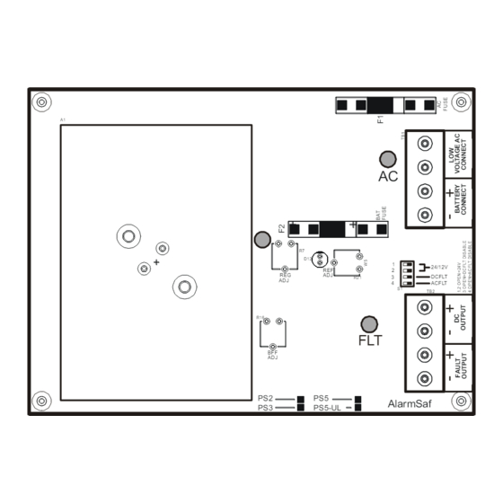
A1
R7
D12
REF
REG
ADJ
ADJ
R16
BFF
ADJ
PS2
PS5
PS3
PS5-UL
Model PS2/3/5
Power Supply / Battery Charger
Operating and Installation Instructions
AC
+
1
24/12V
2
DC FLT
3
R2 1
4
AC FLT
S 1
TB2
+
FLT
+
AlarmSaf
52-133 Rev B.01
Table of
Contents
Previous
Page
Next
Page
1
2
3
4
5
Advertisement
Table of Contents
Need help?
Do you have a question about the PS2 and is the answer not in the manual?
Ask a question
Questions and answers
Subscribe to Our Youtube Channel
Related Manuals for Alarm SAF PS2
Battery Charger Alarm SAF PS5 Operating And Installation Instructions
Power supply battery charger (16 pages)
Battery Charger Alarm SAF CPS2 Operating And Installation Instructions
(18 pages)
This manual is also suitable for:
Ps3
Ps5
Table of Contents
Print
Rename the bookmark
Delete bookmark?
Delete from my manuals?
Login
Sign In
OR
Sign in with Facebook
Sign in with Google
Upload manual
Upload from disk
Upload from URL


Need help?
Do you have a question about the PS2 and is the answer not in the manual?
Questions and answers