Table of Contents
Advertisement
www.epicfit.com
Model No. EPEL19912.0
Serial No.
USER’'S MANUAL
Write the serial number in the space
above for reference.
Serial Number Decal
(on underside of frame)
QUESTIONS?
If you have questions, or if parts
are damaged or missing, DO NOT
CONTACT THE STORE; please
contact Customer Care.
IMPORTANT: Please register this
product (see the limited warranty
on the back cover of this manual)
before contacting Customer Care.
VISIT OUR WEBSITE:
www.epicfit.com
Chat: Mon.––Fri. 6 a.m.––7 p.m. MT
CALL:
1-855-EPIC-FIT (1-855-374-2348)
Mon.––Fri. 6 a.m.––7 p.m. MT
EMAIL:
productsupport@epicfit.com
CAUTION
Read all precautions and instruc-
tions in this manual before using
this equipment. Keep this manual
for future reference.
Advertisement
Table of Contents

Related Manuals for Epic A30E EPEL19912.0


Summary of Contents for Epic A30E EPEL19912.0
- Page 1 Customer Care. VISIT OUR WEBSITE: www.epicfit.com Chat: Mon.––Fri. 6 a.m.––7 p.m. MT CALL: 1-855-EPIC-FIT (1-855-374-2348) Mon.––Fri. 6 a.m.––7 p.m. MT EMAIL: productsupport@epicfit.com CAUTION Read all precautions and instruc- tions in this manual before using this equipment.
-
Page 2: Table Of Contents
TABLE OF CONTENTS WARNING DECAL PLACEMENT ............. . . 2 IMPORTANT PRECAUTIONS . -
Page 3: Important Precautions
IMPORTANT PRECAUTIONS WARNING: To reduce the risk of burns, fire, electric shock, or injury to persons, read all important precautions and instructions in this manual and all warnings on the elliptical before using the elliptical. ICON assumes no responsibility for personal injury or property damage sustained by or through the use of this product. -
Page 4: Before You Begin
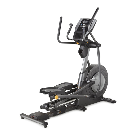
BEFORE YOU BEGIN Thank you for selecting the revolutionary EPIC A30E manual. To help us assist you, note the product model ™™ elliptical. The A30E elliptical provides an impressive number and serial number before contacting us. The selection of features designed to make your workouts model number and the location of the serial number at home more effective and enjoyable. -
Page 5: Part Identification Chart
PART IDENTIFICATION CHART Use the drawings below to identify the small parts needed for assembly. The number in parentheses below each drawing is the key number of the part, from the PART LIST near the end of this manual. The number following the key number is the quantity needed for assembly. -
Page 6: Assembly
•• Left and right parts are marked ““L”” or ““Left”” and video, go to ““R”” or ““Right.”” http://productvideo.co/ assembly/dsg/epic or •• To identify small parts, see page 5. use your mobile phone or smartphone to read In addition to the included tool(s), assembly... - Page 7 3. Tip: Avoid pinching the Sensor Wire Harness (155). Avoid pinching Set a sturdy piece of packing material under the the Sensor Wire rear of the Frame (1). Have a second person Harness (155) hold the Frame to prevent it from tipping while you complete this step.
- Page 8 5. Identify the Lower Upright Cover (80), which has a large oval hole in it. Orient the Lower Upright Cover (80), the Shield Cover (75), and the Upright (4) as shown. Slide the Lower Upright Cover and the Shield Cover upward onto the Upright.
-
Page 9: Arm (58) And Orient Them As Shown
7. Tip: Avoid pinching the Main Wire Harness (110). Slide the Upright (4) onto the Frame (1). Attach Avoid pinching the Upright with seven M8 x 16mm Screws (72); the Main Wire do not fully tighten the Screws yet. Harness (110) Do not press the Shield Cover (75) into place yet. - Page 10 9. Using a plastic bag to keep your fingers clean, apply a generous amount of the included Grease grease to the Arm Axle (35) and to two Wave Washers (95). Insert the Arm Axle (35) into the Upright (4) and center it.
- Page 11 11. Tip: Avoid pinching the wires in the Right and Left Handlebars (83, 87). Attach the Right Handlebar (83) to the right side of the Console Bracket (62) with three M8 x 16mm Screws (72). Repeat this step with the Left Handlebar (87). Then, remove the packaging from the wires on the Right and Left Handlebars (83, 87).
- Page 12 13. Have a second person hold the Console (7) near the Console Bracket (62). Connect the Ground Wire (119) to the matching wire on the Console (7). Then, insert all of the Avoid pinching wires on the Console downward through the the wires indicated hole in the Console Bracket (62).
- Page 13 15. Slide the Lower Upright Cover (80) upward, and attach it to the Upright (4) with two M4 x 16mm Screws (104). 16. Attach the Accessory Tray Base (8) to the Upright (4) with two M4 x 16mm Screws (104). 17.
- Page 14 18. Press the Upper Upright Cover (91) onto the Lower Upright Cover (80). 19. Identify the Right Arm Upper Cover (67) and the Right Arm Lower Cover (68). Attach the Right Arm Upper Cover (67) to the Right Upper Body Leg (36) with an M4 x 16mm Screw (104).
- Page 15 21. While a second person tips the elliptical to the left and holds it, attach a Stabilizer Cap (134) to the right side of the Frame (1) with two M4 x 16mm Screws (104). Next, tighten a Leveling Foot (92) into the Frame (1) in the indicated location.
-
Page 16: How To Use The Elliptical
HOW TO USE THE ELLIPTICAL HOW TO PLUG IN THE POWER CORD A temporary adapter may 2-pole Receptacle This product must be grounded. If it should malfunc- be used to tion or break down, grounding provides a path of least connect the Adapter resistance for electric current to reduce the risk of... - Page 17 HOW TO MOVE THE ELLIPTICAL HOW TO ADJUST THE POSITIONS OF THE PEDALS Due to the size and weight of the elliptical, moving it requires two persons. Stand in front of the elliptical, Each pedal can be adjusted to several positions. To hold the upright, and place one foot against one of the adjust each pedal, lift the pedal and turn the pedal wheels.
- Page 18 HOW TO LEVEL THE ELLIPTICAL HOW TO EXERCISE ON THE ELLIPTICAL If the elliptical rocks slightly on your floor during use, To mount the elliptical, hold the upper body arms or turn one or both of the leveling feet beneath the rear the handlebars and step onto the pedal that is in the stabilizer until the rocking motion is eliminated.
- Page 19 CONSOLE DIAGRAM FEATURES OF THE CONSOLE The console also offers user-defined workouts that allow you to create your own workouts and store them The advanced console offers an array of features in memory for future use. designed to make your workouts more effective and enjoyable.
- Page 20 HOW TO TURN ON THE POWER HOW TO SET UP THE CONSOLE IMPORTANT: If the elliptical has been exposed to Before using the elliptical for the first time, set up the cold temperatures, allow it to warm to room tem- console.
- Page 21 HOW TO USE THE MANUAL MODE Calories per Hour (Calories/Hr)——This display mode will show the approximate number of calories 1. Begin pedaling or press any button on the you are burning per hour. console to turn on the console. Distance——This display mode will show the dis- See HOW TO TURN ON THE POWER on tance that you have pedaled in miles or kilometers.
- Page 22 To pause the manual mode or a workout, stop ped- 5. Measure your heart rate if desired. aling. The time will pause in the display. To resume the manual mode or the workout, simply resume If there are sheets of plastic on the metal pedaling.
- Page 23 HOW TO USE AN ONBOARD WORKOUT If the resistance level or incline level for the current segment is too high or too low, you can manu- 1. Begin pedaling or press any button on the ally override the setting by pressing the Quick console to turn on the console.
- Page 24 HOW TO USE A SET-A-GOAL WORKOUT HOW TO CREATE A USER-DEFINED WORKOUT 1. Begin pedaling or press any button on the 1. Begin pedaling or press any button on the console to turn on the console. console to turn on the console. See HOW TO TURN ON THE POWER on See HOW TO TURN ON THE POWER on page 20.
- Page 25 HOW TO USE A USER-DEFINED WORKOUT automatically adjust to the incline level pro- grammed for the next segment. 1. Begin pedaling or press any button on the console to turn on the console. The workout will continue in this way until the last segment ends.
- Page 26 HOW TO USE AN IFIT LIVE WORKOUT of calories you will burn during the workout and a profile of the resistance settings of the workout. Note: To use an iFit workout, you must have access to a wireless network (see page 27). An iFit account is Note: The calorie goal is an estimate of the also required (see step 4 on page 20).
- Page 27 HOW TO CHANGE CONSOLE SETTINGS Units——The selected unit of measurement will appear in the matrix. To change the unit of mea- The console features a settings mode that allows you surement, press the Enter button. To view distance to view usage information, to personalize console set- in miles, select ENGLISH.
- Page 28 iFit User Setup——To set up a different iFit account, Press the up, down, left, and right buttons to high- but maintain the existing wireless connection, fol- light the desired letter or number. Then, press the low the instructions in the matrix. Enter button to select the letter, number, or symbol.
- Page 29 Then, cycle the power of the elliptical: press the Your browser will load a web page. If the web page power switch on the elliptical to the off position, does not appear, double-check the IP address and wait for several seconds, and then press the power the previous instructions of this step.
-
Page 30: Fcc Information
FCC INFORMATION This equipment has been tested and found to comply with the limits for a Class B digital device, pursuant to part 15C and part 18 of the FCC Rules. These limits are designed to provide reasonable protection against harmful interference in a residential installation. -
Page 31: Maintenance And Troubleshooting
MAINTENANCE AND TROUBLESHOOTING IMPORTANT: Servicing other than the procedures HOW TO ADJUST THE DRIVE BELT described below should be performed only by an authorized service representative. If the pedals slip while you are pedaling, even while the resistance is adjusted to the highest level, the drive Inspect and tighten all parts of the elliptical regularly. - Page 32 HOW TO ADJUST THE REED SWITCH Loosen, but do not remove, the two indicated M4 x 16mm Screws (104). Slide the Reed Switch (38) If the console does not display correct feedback, the slightly closer to or away from the Magnet (43). Then, reed switch should be adjusted.
-
Page 33: Exercise Guidelines
EXERCISE GUIDELINES Burning Fat——To burn fat effectively, you must exer- WARNING: cise at a low intensity level for a sustained period of Before beginning this time. During the first few minutes of exercise, your or any exercise program, consult your physi- body uses carbohydrate calories for energy. - Page 34 SUGGESTED STRETCHES The correct form for several basic stretches is shown at the right. Move slowly as you stretch; never bounce. 1. Toe Touch Stretch Stand with your knees bent slightly and slowly bend forward from your hips. Allow your back and shoulders to relax as you reach down toward your toes as far as possible.
-
Page 35: Part List
PART LIST Model No. EPEL19912.0 R0912A Key No. Qty. Description Key No. Qty. Description Frame Roller Rear Stabilizer Cover Console Knob Ramp Axle Cover Upright Left Arm Upper Cover Rear Stabilizer Left Arm Lower Cover Front Stabilizer Upper Handlebar Cover Console Roller Arm/Pedal Arm Bushing Accessory Tray Base... - Page 36 Key No. Qty. Description Key No. Qty. Description Idler Screw Stabilizer Cap M8 Locknut Left Pedal Adjustment Bracket Ultrasonic Sensor Bracket Pedal Arm Flex Bracket M4 x 16mm Screw Flex Bracket Cover M8 x 16mm Hex Screw Left Pedal Plate Small Pulley Spacer Right Pedal Plate Large Standoff...
-
Page 37: Exploded Drawing
EXPLODED DRAWING A Model No. EPEL19912.0 R0912A... - Page 38 EXPLODED DRAWING B Model No. EPEL19912.0 R0912A...
- Page 39 EXPLODED DRAWING C Model No. EPEL19912.0 R0912A...
-
Page 40: Ordering Replacement Parts
ORDERING REPLACEMENT PARTS To order replacement parts, please see the front cover of this manual. To help us assist you, be prepared to provide the following information when contacting us: •• the model number and serial number of the product (see the front cover of this manual) ••...
Need help?
Do you have a question about the A30E EPEL19912.0 and is the answer not in the manual?
Questions and answers
Mine keeps saying "not connecting check manual" and it keeps making a peeping sound