
Subscribe to Our Youtube Channel
Related Manuals for STEMME S6


Summary of Contents for STEMME S6
- Page 1 STEMME TSA-M MAINTENANCE MANUAL MAINTENANCE MANUAL STEMME TSA-M MODELS: S6 S6-RT Doc.-No. P500-006.000 Rev. 9 Issued: December 2010 STEMME 2010...
- Page 2 STEMME TSA-M MAINTENANCE MANUAL...
- Page 3 Documentary Changes 01.11.2011 24, 71, 91 Introduction Solar Panel (Option) Introduction Retractable Landing 18.11.2011 Gear, 900 kg MTOW (Model S6-RT), Documentary Changes (incl. change of header all pages) 28.02.2012 100h TBO Front Gear Box 16.03.2012 10, 11 Introduction Wing Folding Device (Option) 04.05.2012...
- Page 4 STEMME TSA-M MAINTENANCE MANUAL...
- Page 5 STEMME TSA-M MAINTENANCE MANUAL CHAPTER 00 INTRODUCTION...
- Page 6 STEMME TSA-M MAINTENANCE MANUAL...
-
Page 7: Table Of Contents
STEMME TSA-M MAINTENANCE MANUAL TABLE OF CONTENTS Chapter Section Title Subject Page INTRODUCTION .....................00-00-00 General 00-00-00 List of Vendor Technical Publications 00-00-00 Structure of Maintenance Manual 00-00-00 Using the Maintenance Manual 00-00-00 List of Chapters 00-00-00 List of Effective Pages... - Page 8 STEMME TSA-M MAINTENANCE MANUAL...
-
Page 9: Introduction
MAINTENANCE MANUAL INTRODUCTION 1. General This maintenance manual provides necessary for the maintenance of the S6 information to the maintenance personnel. It contains detailed descriptions of the systems, troubleshooting, and maintenance practices. In this handbook are only contained maintenance practices about jobs, which are to be practiced at the aircraft itself: e.g. - Page 10 STEMME TSA-M MAINTENANCE MANUAL Manual No./Part No. Manual Title Vendor ROTAX Part. No. 899470, Illustrated Parts Catalog ROTAX 912 Rev. 0, December 01/2007, or ROTAX Aircraft Engines A/F/S/UL/ULS/ULSFR and 914 F/UL a later Revision ROTAX Part. No. 899643, Rev. 01, February 01/2008, or Operator’s Manual for ROTAX 914 Series ROTAX Aircraft Engines...
-
Page 11: Structure Of Maintenance Manual
STEMME TSA-M MAINTENANCE MANUAL 3. Structure of the Maintenance Manual The MM has been prepared in accordance with the Air Transport Association (ATA) Specification Number 100 for Manufacturers Technical Data. Division of Subject Matter The MM is divided into 5 major sections. Each of these sections is subdivided into chapters. A list of effective pages and the table of contents are provided at the beginning of each MM chapter. - Page 12 STEMME TSA-M MAINTENANCE MANUAL (3) When the section/subsystem element number is followed with zeros in the subject/unit element number (28-20-00), the information is applicable to subsystem within the system. (4) The subject/unit element number is used to identify information applicable to units within the subsystems.
-
Page 13: Using The Maintenance Manual
STEMME TSA-M MAINTENANCE MANUAL (2) Each chapter begins with: Title Table of Contents Figures The figures within the sections of a chapter are numbered in accordance with the appropriate page number block. Numbering is beginning by one (1) and continuous. - Page 14 STEMME TSA-M MAINTENANCE MANUAL Revisions (1) Maintenance manual revisions, result by different reasons (regulation changes, technical changes, typographical errors and so on), will be published regularly. This manual has been prepared in loose-leaf form for ease in inserting revisions. The ATA format in presentation and numbering allows quick reference to data in each section.
- Page 15 STEMME TSA-M MAINTENANCE MANUAL WARNINGS, CAUTIONS, and NOTES If maintenance operations on the airplane are practiced, general safety and maintenance rules must be always considered. In addition, the MM contains adjuncts to the text used to highlight or emphasize important and critical instructions.
- Page 16 STEMME TSA-M MAINTENANCE MANUAL...
-
Page 17: List Of Chapters
STEMME TSA-M MAINTENANCE MANUAL 5. List of Chapters Chapter Title Date GENERAL Introduction Mar 16/12 General Nov 18/11 Airworthiness Feb 28/12 Time Limits / Maintenance Checks May 04/12 Dimensions and Areas Nov 18/11 Lifting & Shoring Nov 18/11 Leveling and Weighing... - Page 18 STEMME TSA-M MAINTENANCE MANUAL 5. List of Chapters (continued) Chapter Title Date POWER PLANT Power Plant May 04/12 Engine Drive Section May 04/12 Ignition Nov 18/11 Engine Cooling System May 04/12 Engine Controls Nov 18/11 Engine Indicating Nov 18/11 Exhaust...
- Page 19 Nov 18/11 02-00-00 Nov 18/11 S6-RT 06-00-00 Nov 18/11 02-00-00 Nov 18/11 S6-RT 06-10-00 Nov 18/11 S6, 001 - 012 02-00-00 Nov 18/11 S6-RT 06-10-00 Nov 18/11 S6, 001 - 012 04-Title 06-10-00 Nov 18/11 S6, 001 - 012 04-ROR...
-
Page 20: List Of Effective Pages
STEMME TSA-M MAINTENANCE MANUAL 6. List of Effective Pages (continued) CHAPTER/ CHAPTER/ SECTION/ SECTION/ SUBJECT PAGE DATE EFFECTIVITY SUBJECT PAGE DATE EFFECTIVITY 06-30-00 Nov 18/11 S6-RT 10-11-00 Nov 18/11 06-30-00 Nov 18/11 S6-RT 10-20-00 Nov 18/11 06-30-00 Nov 18/11 S6-RT... - Page 21 STEMME TSA-M MAINTENANCE MANUAL 6. List of Effective Pages (continued) CHAPTER/ CHAPTER/ SECTION/ SECTION/ SUBJECT PAGE DATE EFFECTIVITY SUBJECT PAGE DATE EFFECTIVITY 12-10-00 May 04/12 S6-RT 20-10-00 Nov 18/11 12-11-00 Nov 18/11 20-10-00 Nov 18/11 12-11-00 Nov 18/11 20-10-00 Nov 18/11...
- Page 22 STEMME TSA-M MAINTENANCE MANUAL 6. List of Effective Pages (continued) CHAPTER/ CHAPTER/ SECTION/ SECTION/ SUBJECT PAGE DATE EFFECTIVITY SUBJECT PAGE DATE EFFECTIVITY 23-50-00 Nov 18/11 Prof. Avionics 25-10-00 Nov 18/11 011 - 999 23-50-00 Nov 18/11 Prof. Avionics 25-10-00 Nov 18/11...
- Page 23 STEMME TSA-M MAINTENANCE MANUAL 6. List of Effective Pages (continued) CHAPTER/ CHAPTER/ SECTION/ SECTION/ SUBJECT PAGE DATE EFFECTIVITY SUBJECT PAGE DATE EFFECTIVITY 28-20-00 Nov 18/11 32-40-00 Nov 18/11 28-40-00 Nov 18/11 32-40-00 Nov 18/11 28-40-00 Nov 18/11 32-40-00 Nov 18/11...
- Page 24 STEMME TSA-M MAINTENANCE MANUAL 6. List of Effective Pages (continued) CHAPTER/ CHAPTER/ SECTION/ SECTION/ SUBJECT PAGE DATE EFFECTIVITY SUBJECT PAGE DATE EFFECTIVITY 32-40-00 Nov 18/11 S6-RT 51-Title 32-40-00 Nov 18/11 S6-RT 51-TOC Nov 18/11 32-40-00 Nov 18/11 S6-RT 51-00-00 Nov 18/11...
- Page 25 STEMME TSA-M MAINTENANCE MANUAL 6. List of Effective Pages (continued) CHAPTER/ CHAPTER/ SECTION/ SECTION/ SUBJECT PAGE DATE EFFECTIVITY SUBJECT PAGE DATE EFFECTIVITY 57-20-00 Nov 18/11 71-10-00 Nov 18/11 57-20-00 Nov 18/11 71-10-00 Nov 18/11 Solar Panel 57-30-00 Nov 18/11 71-10-00...
- Page 26 STEMME TSA-M MAINTENANCE MANUAL 6. List of Effective Pages (continued) CHAPTER/ CHAPTER/ SECTION/ SECTION/ SUBJECT PAGE DATE EFFECTIVITY SUBJECT PAGE DATE EFFECTIVITY 75-00-00 May 04/12 024 - 999 80-00-00 Nov 18/11 75-00-00 May 04/12 024 - 999 80-10-00 Nov 18/11...
- Page 27 STEMME TSA-M MAINTENANCE MANUAL CHAPTER 02 GENERAL...
- Page 28 STEMME TSA-M MAINTENANCE MANUAL...
-
Page 29: Chapter Section Subject Page
STEMME TSA-M MAINTENANCE MANUAL TABLE OF CONTENTS Chapter Section Title Subject Page GENERAL ......................02-00-00 Introduction 02-00-00 General Description 02-00-00 Technical Data 02-00-00 Page 01 02 - TOC Nov 18/11... - Page 30 STEMME TSA-M MAINTENANCE MANUAL...
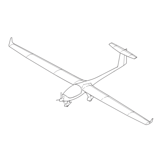
- Page 31 Hirth air brakes and inboard and outboard ailerons. The tail unit is designed as a T-tail. The S6 has a fixed tricycle type landing gear with a steerable nose gear. The main gear is equipped with single disc hydraulic brake assemblies. Strut and wheel fairings are provided to improve the aerodynamic properties.
- Page 32 STEMME TSA-M MAINTENANCE MANUAL Aircraft - Overview Figure 01 EFFECTIVITY Page 02 Model S6 02-00-00 Nov 18/11...
- Page 33 Tricycle, fixed Wheel Track 1889 mm 6.2 ft. Wheel Base 1970 mm 6.5 ft. Performances For performance data refer to the applicable Flight Manual (refer to 00-00-00, List of Vendor Technical Publications). EFFECTIVITY Page 03 Model S6 02-00-00 Nov 18/11...
- Page 34 STEMME TSA-M MAINTENANCE MANUAL...
- Page 35 Hirth air brakes and inboard and outboard ailerons. The tail unit is designed as a T-tail. The S6 has a retractable tricycle type landing gear with a steerable nose gear. All three landing gear legs are equipped with separate gear doors to cover each of the landing gear legs and the wheel wells completely and aerodynamically.
- Page 36 STEMME TSA-M MAINTENANCE MANUAL Aircraft - Overview Figure 01 EFFECTIVITY Page 02 Model S6-RT 02-00-00 Nov 18/11...
- Page 37 Tricycle, retractable Wheel Track 1889 mm 6.2 ft. Wheel Base 1970 mm 6.5 ft. Performances For performance data refer to the applicable Flight Manual (refer to 00-00-00, List of Vendor Technical Publications). EFFECTIVITY Page 03 Model S6-RT 02-00-00 Nov 18/11...
- Page 38 STEMME TSA-M MAINTENANCE MANUAL...
- Page 39 STEMME TSA-M MAINTENANCE MANUAL CHAPTER 04 AIRWORTHINESS LIMITATIONS...
- Page 40 STEMME TSA-M MAINTENANCE MANUAL...
- Page 41 Signature and Date 20.12.2010 First Issue 18.11.2011 04-00-01, Introduction Retractable Landing p. 02 Gear, 900kg MTOW (Model S6-RT) The technical content of this revision is approved under the authority of EASA.21J.250 28.02.2012 04-00-01, 100h TBO Front Gear Box p. 01...
- Page 42 STEMME TSA-M MAINTENANCE MANUAL...
- Page 43 STEMME TSA-M MAINTENANCE MANUAL TABLE OF CONTENTS Chapter Section Title Subject Page AIRWORTHINESS LIMITATIONS - GENERAL ..........04-00-00 Introduction 04-00-00 General Description 04-00-00 COMPONENT LIFE LIMITS................04-00-01 General 04-00-01 Component Life Limits 04-00-01 Page 01 04 - TOC Nov 18/11...
- Page 44 STEMME TSA-M MAINTENANCE MANUAL...
- Page 45 This chapter sets out the mandatory replacement time, and so far as is necessary, inspection periods for structure as well as structural inspection procedures for the S6. It contains information about the service life of such parts or components that must be overhauled or replaced at specific flight time limits.
- Page 46 STEMME TSA-M MAINTENANCE MANUAL...
- Page 47 STEMME TSA-M MAINTENANCE MANUAL CHAPTER 04 AIRWORTHINESS LIMITATIONS - FAA -...
- Page 48 STEMME TSA-M MAINTENANCE MANUAL...
- Page 49 Descriptions of Revisions Signature and Date 20.12.2010 First Issue 18.11.2011 04-00-01, Introduction Retractable Landing p. 02 Gear, 900kg MTOW (Model S6-RT) 28.02.2012 04-00-01, 100h TBO Front Gear Box p. 01 Page 01 - FAA - 04 - RECORD OF REVISIONS...
- Page 50 STEMME TSA-M MAINTENANCE MANUAL...
- Page 51 STEMME TSA-M MAINTENANCE MANUAL TABLE OF CONTENTS Chapter Section Title Subject Page AIRWORTHINESS LIMITATIONS - GENERAL ..........04-00-00 Introduction 04-00-00 General Description 04-00-00 COMPONENT LIFE LIMITS................04-00-01 General 04-00-01 Component Life Limits 04-00-01 Page 01 04 - TOC - FAA - Nov 18/11...
- Page 52 STEMME TSA-M MAINTENANCE MANUAL...
- Page 53 This chapter sets out the mandatory replacement time, and so far as is necessary, inspection periods for structure as well as structural inspection procedures for the S6. It contains information about the service life of such parts or components that must be overhauled or replaced at specific flight time limits.
- Page 54 STEMME TSA-M MAINTENANCE MANUAL...
- Page 55 By the process of fatigue tests and their results, the component life limits may be changed. These changes will be announced by STEMME in such cases. Replace the components shown in the following table, on or before reaching the applicable life limits: Cha.
- Page 56 (3) The TBO expires in each case of: (a) impact stop (possible ground touch of the propeller); (b) Non-observance of the periodical inspections as they are fixed in the Maintenance Manual; non-authorized replacement of essential parts. EFFECTIVITY Page 02 Page 02 Model S6 04-00-01 04-00-01 Nov 18/11...
- Page 57 (5) Overhaul of the fuel check valves mean, that the check valves will be checked visually after 5 years. During this check they shall be especially inspected for signs of brittleness or change in color. In such a case the parts shall be replaced. EFFECTIVITY Page 03 Model S6 04-00-01 Nov 18/11...
- Page 58 STEMME TSA-M MAINTENANCE MANUAL...
- Page 59 By the process of fatigue tests and their results, the component life limits may be changed. These changes will be announced by STEMME in such cases. Replace the components shown in the following table, on or before reaching the applicable life limits: Cha.
- Page 60 (1) Extension of service life exceeding 6000 h can be achieved only for individual airplanes after a comprehensive inspection of the airframe carried out by the manufacturer according to an approved program. EFFECTIVITY Page 02 Page 02 Model S6-RT 04-00-01 04-00-01 Nov 18/11 Feb 26/10...
- Page 61 (5) Overhaul of the fuel check valves mean, that the check valves will be checked visually after 5 years. During this check they shall be especially inspected for signs of brittleness or change in color. In such a case the parts shall be replaced. EFFECTIVITY Page 03 Model S6-RT 04-00-01 Nov 18/11...
- Page 62 STEMME TSA-M MAINTENANCE MANUAL...
- Page 63 STEMME TSA-M MAINTENANCE MANUAL CHAPTER 05 TIME LIMITS / MAINTENANCE CHECKS...
- Page 64 STEMME TSA-M MAINTENANCE MANUAL...
- Page 65 05-10-00 SCHEDULED MAINTENANCE CHECKS............05-20-00 General 05-20-00 Inspection Intervals 05-20-00 Definition Periodic Inspections 05-20-00 Definition Special Hours Inspections 05-20-00 Inspection Time Intervals Chart S6 05-20-00 DAILY INSPECTIONS ..................05-30-00 General 05-30-00 Preflight Inspection 05-30-00 After Flights 05-30-00 UNSCHEDULED MAINTENANCE CHECKS ..........05-50-00 General...
- Page 66 STEMME TSA-M MAINTENANCE MANUAL...
-
Page 67: Time Limits / Maintenance Checks - General
Section 05-20-00 Scheduled Maintenance Checks. This section contains information about recommended scheduled maintenance and inspections. Recommended maintenance and Inspections of the systems and components of the S6 as well as the relevant intervals are contained in a chart. Section 05-30-00 Daily Inspections. The preflight check and the checks after flights are described. - Page 68 STEMME TSA-M MAINTENANCE MANUAL...
-
Page 69: Time Limits
STEMME TSA-M MAINTENANCE MANUAL TIME LIMITS 1. General This section contains part manufacturer recommended time limits for replacement and overhaul of parts. 2. Replacement and Overhaul Schedule The following parts or components must be replaced or overhauled at the specified intervals. - Page 70 STEMME TSA-M MAINTENANCE MANUAL and/or service life is intended) and will be notified by a new revision of this chapter. (2) The TBO expires in each case of: (a) impact stop (possible ground touch of the propeller); (b) Non-observance of the periodical inspections as they are fixed in the Maintenance Manual;...
-
Page 71: Scheduled Maintenance Checks
3. Definition Periodic Inspections Periodic inspections are those which must be performed every 100, 200, 600 and 1000 engine operating hours. They have to be carried out in accordance with the following S6 Inspection Time Interval Chart. This means for example that every 100 hr of operation (100, 200, 300 hr ...) a 100 hr check and all 200 hr (200, 400, 600 hr ...) additional checks as per maintenance interval chart must be carried out. - Page 72 STEMME TSA-M MAINTENANCE MANUAL 5. S6 Inspection Time Interval Chart The maintenance and checks listed in the following chart are to be practiced in the specified periods and are to be documented in a required manner. Page 02 05-20-00 Nov 18/11...
- Page 73 STEMME TSA-M MAINTENANCE MANUAL S6 Inspection Time Intervals Chart: Reference Initials Type and Subject of Inspection 5.1.1 General Check service life limits of all components and installed equipment. Thoroughly clean a/c. Remove or open all necessary inspection plates, access doors, fairings and cowlings.
- Page 74 STEMME TSA-M MAINTENANCE MANUAL Reference Initials Type and Subject of Inspection Check vent line outlets at end ribs of central wing. Check function and leak tightness of quick-release couplings (supply lines) to and from fuselage. Check all fuel filters and replace if required.
- Page 75 STEMME TSA-M MAINTENANCE MANUAL Reference Initials Type and Subject of Inspection Check security and condition of drive gear cowlings. Clearance allowed (all around): 1 +1.0, -0.5 mm / 0.04 + 0.04, -0.02 in 5.1.4 Cockpit Inspect canopy for damage and check proper function of locking mechanism, grease canopy locks.
- Page 76 STEMME TSA-M MAINTENANCE MANUAL Reference Initials Type and Subject of Inspection Check condition and security of landing gear attachment. Check condition of entire control linkage in the center fuselage. Main battery: Check electrical terminals, condition and security of mounting tray.
- Page 77 STEMME TSA-M MAINTENANCE MANUAL Reference Initials Type and Subject of Inspection 5.1.8 Fuel System Components in the Fuselage Check condition of supply, return and drain lines outside the engine compartment, supply and return lines inside the engine compartment. Check condition, security and function of fuel pumps.
- Page 78 STEMME TSA-M MAINTENANCE MANUAL Reference Initials Type and Subject of Inspection 10. Inspect carburetor sockets for condition, damage. R* 05-20-00 11. Check condition of fuel lines, pressure connection lines and compensating tube assy at the R* 05-20-00 carburetor’s airbox. Check for leakage and correct installation.
- Page 79 STEMME TSA-M MAINTENANCE MANUAL Reference Initials Type and Subject of Inspection 5.1.10 Lubrication System Check condition of oil radiator and oil tank assemblies. Check oil lines (from/to engine and turbocharger) and oil drainline for condition, leakage and correct R* 05-20-00 routing.
- Page 80 STEMME TSA-M MAINTENANCE MANUAL Reference Initials Type and Subject of Inspection 5.1.12 Air Induction System Check condition of air filter. 12-13-00 5.1.13 Engine Controls & Monitoring Throttle and choke: Check end stops of carburetor R* 05-20-00 controls, springs and condition of bowden-cables.
- Page 81 STEMME TSA-M MAINTENANCE MANUAL Reference Initials Type and Subject of Inspection Check blades and all visible hub parts for cracks, MT**/6 deformation, position and security. Check cable routing, cable condition and MT**/6 connection. Check carbon brush block and slip rings for wear.
- Page 82 STEMME TSA-M MAINTENANCE MANUAL Reference Initials Type and Subject of Inspection 5.1.17 Main Landing Gear (Fix L/G) Remove main gear fairings and inspect for damages. Verify the bearings of the wheel shoes are free moveable. Inspect the main gear legs and trailing arms for deformation and possible cracks as a result of an excessive load.
- Page 83 STEMME TSA-M MAINTENANCE MANUAL Reference Initials Type and Subject of Inspection 5.1.19 Flight Instrumentation and Pressure Systems Check condition of pressure system , renew filters/water separators if required. Check condition and function of flight instruments (refer to equipment list). 5.1.20 Electrical System (except for engine and TCU) Check wiring of the electric system.
- Page 84 STEMME TSA-M MAINTENANCE MANUAL...
- Page 85 STEMME TSA-M MAINTENANCE MANUAL Reference Initials Type and Subject of Inspection 5.2.1 Cabin Heating System (Option) Check service life limits of heating system parts together with engine cooling system. Check refrigerant hoses of the heating system. Check Heat Exchanger and magnetic shut-off valve.
- Page 86 STEMME TSA-M MAINTENANCE MANUAL...
- Page 87 STEMME TSA-M MAINTENANCE MANUAL Reference Initials Type and Subject of Inspection 5.3.1 Aerotow Equipment (Option) Remove cover of cockpit middle console to get access to aerotow release lever. Clean aerotow release clutch E22 and check for function and condition. Pay attention to required TBO of aerotow release 05-10-00 clutch.
- Page 88 STEMME TSA-M MAINTENANCE MANUAL...
- Page 89 11. Check main landing gear deflector if clean and free- moving, also at rail (steel frame side). 12. Check all final position micro switches for damage and dirt. EFFECTIVITY Page 01 Model S6-RT 05-20-03 Nov 18/11...
- Page 90 90 bar / 1305 psi ± 8%). Check all hydraulic lines and both pressure reservoir bottles, fittings and hydraulic actuation unit for condition, damage and leakage. EFFECTIVITY Page 02 Model S6-RT 05-20-03 Nov 18/11...
- Page 91 Perform functional test of landing gear emergency extension. Check hydraulic fluid level afterwards (ref. 5.4.4). 5.4.6 Engine Cooling System Check function of cooling radiator fan during engine test run (engine coolant temperature has to stabilize during warm up). EFFECTIVITY Page 03 Model S6-RT 05-20-03 May 04/12...
- Page 92 STEMME TSA-M MAINTENANCE MANUAL...
-
Page 93: Daily Inspections
The pre-flight check must be done before the first flight of the day by the responsible pilot. The walk-around shows the pilot the general condition of the aircraft and its systems. For the pre-flight check procedure, refer to the S6 Airplane Flight Manual, Section 4. 3. Post-Flight Check This check must be performed after the last flight of the day. - Page 94 STEMME TSA-M MAINTENANCE MANUAL...
-
Page 95: Unscheduled Maintenance Checks
Even if no obvious defects are detectable, a visual inspection must be carried out. Examination contains parts of 100 hours inspection listed in the STEMME S6 Inspection Time Intervals Chart (Refer to section "Scheduled Maintenance Checks" of this chapter) concerning the landing gear. - Page 96 STEMME TSA-M MAINTENANCE MANUAL (10) Replace damaged items. (11) Install engine cowling (refer to 72-10-00). (12) Perform an engine test run (refer to 05-20-00). Violent Stop of the Engine In event that the propeller was touching ground or the engine was inadvertently stopped violently (shock loading) the engine with the propeller gear box must be disassembled and inspected by an authorized workshop.
- Page 97 Even if no obvious defects are detectable, a visual inspection must be carried out. Examination contains parts of 100 hours inspection listed in the STEMME S6 Inspection Time Intervals Chart (Refer to section "Scheduled Maintenance Checks" of this chapter) concerning the landing gear.
- Page 98 ONLY QUALIFIED TECHNICIANS (AUTHORIZED BY AVIATION AUTHORITY AND AFTER SUCCESSFUL ATTENDANCE OF THE RELEVANT ROTAX TRAINING COURSE) ARE AUTHORIZED TO PERFORM THIS WORK. Check additional equipment (external alternator, hydraulic governor, ignition unit, coolant and oil hoses) for damage. EFFECTIVITY Page 202 Model S6-RT 05-50-00 Nov 18/11...
- Page 99 STEMME TSA-M MAINTENANCE MANUAL CHAPTER 06 DIMENSIONS AND AREAS...
- Page 100 STEMME TSA-M MAINTENANCE MANUAL...
- Page 101 STEMME TSA-M MAINTENANCE MANUAL TABLE OF CONTENTS Chapter Section Title Subject Page DIMENSIONS AND AREAS - GENERAL .............06-00-00 Introduction 06-00-00 General Description 06-00-00 AIRCRAFT DIMENSIONS AND AREAS............06-10-00 General 06-10-00 Dimensions and Areas 06-10-00 Control Surface Moments and Weights 06-10-00 AIRCRAFT ZONING ..................06-20-00...
- Page 102 STEMME TSA-M MAINTENANCE MANUAL...
-
Page 103: Dimensions And Areas - General
1. Introduction This chapter provides information about dimensions and control surface travel and tolerances of the S6. Furthermore, this chapter contains information about aircraft zoning, access and inspection plates. Dimensions are presented to aid the operator and/or maintenance personnel in ground handling the aircraft, e.g. - Page 104 STEMME TSA-M MAINTENANCE MANUAL...
-
Page 105: Aircraft Dimensions And Areas
Down Travel (inboard) (+) 5.3° Flaps (both): Area 1.57 m 16.9 ft Flap Setting (Ground, LH, RH): Cruise - 8.5° Neutral +5.0° ±1° Takeoff / Landing I +18.5° Landing II +25° EFFECTIVITY Page 01 Model S6, 001 - 012 06-10-00 Nov 18/11... - Page 106 STEMME TSA-M MAINTENANCE MANUAL 2.45 (8.04) 1.97 (6.5) 8.52 (27.95) 18.00 (59.06) 1.89 (6.2) Aircraft Dimensions [ m (ft.)] Figure 1 EFFECTIVITY Page 02 Model S6, 001 - 012 06-10-00 Nov 18/11...
-
Page 107: Control Surface Moments And Weights
990 - 1210 g (2.18 - 2.67 lb) NOTE: All given values for control surface moments and weights represent the values for single control surfaces without external hinges and brackets installed. EFFECTIVITY Page 03 Model S6, 001 - 012 06-10-00 Nov 18/11... - Page 108 STEMME TSA-M MAINTENANCE MANUAL...
- Page 109 Down Travel (inboard) (+) 5.3° Flaps (both): Area 1.57 m 16.9 ft Flap Setting (Ground, LH, RH): Cruise - 4.0° Neutral +5.0° ±1° Takeoff / Landing I +18.5° Landing II +25° EFFECTIVITY Page 01 Model S6, 013 - 999 06-10-00 Nov 18/11...
- Page 110 STEMME TSA-M MAINTENANCE MANUAL 2.45 (8.04) 1.97 (6.5) 8.52 (27.95) 18.00 (59.06) 1.89 (6.2) Aircraft Dimensions [ m (ft.)] Figure 1 EFFECTIVITY Page 02 Model S6, 013 - 999 06-10-00 Nov 18/11...
- Page 111 1330 - 1550 g (2.93 - 3.42 lb) NOTE: All given values for control surface moments and weights represent the values for single control surfaces without external hinges and brackets installed. EFFECTIVITY Page 03 Model S6, 013 - 015 06-10-00 Nov 18/11...
- Page 112 STEMME TSA-M MAINTENANCE MANUAL...
- Page 113 1330 - 1550 g (2.93 - 3.42 lb) NOTE: All given values for control surface moments and weights represent the values for single control surfaces without external hinges and brackets installed. EFFECTIVITY Page 03 Model S6, 016 - 999 06-10-00 Nov 18/11...
- Page 114 STEMME TSA-M MAINTENANCE MANUAL...
- Page 115 ( - ) 10.5° Down Travel (inboard) (+) 5.3° Flaps (both): Area 1.57 m 16.9 ft Flap Setting (Ground, LH, RH): Cruise - 4.0° Neutral +5.0° ±1° Takeoff / Landing I +18.5° Landing II +25° EFFECTIVITY Page 01 Model S6-RT 06-10-00 Nov 18/11...
- Page 116 STEMME TSA-M MAINTENANCE MANUAL 2.45 (8.04) 1.97 (6.5) 8.52 (27.95) 18.00 (59.06) 1.89 (6.2) Aircraft Dimensions [ m (ft.)] Figure 1 EFFECTIVITY Page 02 Model S6-RT 06-10-00 Nov 18/11...
- Page 117 40.5 - 51.5 Ncm (3.6 in.lb - 4.6 in.lb) 1330 - 1550 g (2.93 - 3.42 lb) NOTE: All given values for control surface moments and weights represent the values for single control surfaces without external hinges and brackets installed. EFFECTIVITY Page 03 Model S6-RT 06-10-00 Nov 18/11...
- Page 118 STEMME TSA-M MAINTENANCE MANUAL...
-
Page 119: Aircraft Zoning
MAINTENANCE MANUAL AIRCRAFT ZONING 1. General The S6 is divided into numbered zones to provide a method for locating components or parts throughout the aircraft. This Aircraft zoning corresponds to the usual standard. The zones are identified by a (3) three-digit number. The first digit in the sequence denotes the... - Page 120 STEMME TSA-M MAINTENANCE MANUAL Instrument Panel Aircraft Zones Figure 1 Page 02 06-20-00 Nov 18/11...
- Page 121 MAINTENANCE MANUAL ACCESS & INSPECTION PLATES 1. General Accesses / inspection plates on the S6 are used to gain access to various systems, components and parts of structure during maintenance and for inspection. The access and inspection plates are designated logically.
-
Page 122: Access/Inspection Plates
STEMME TSA-M MAINTENANCE MANUAL 100AT 200CL 300BL 200EB 100BB 200BT 300AT 200AT Access / Inspection Plates Figure 1 Page 02 06-30-00 Nov 18/11... - Page 123 STEMME TSA-M MAINTENANCE MANUAL 610BB 610AB 510AB 620AB 520AB 200EB 200FB 300CB Access / Inspection Plates Figure 1(2) Page 03 06-30-00 Nov 18/11...
- Page 124 STEMME TSA-M MAINTENANCE MANUAL...
-
Page 125: General
MAINTENANCE MANUAL ACCESS & INSPECTION PLATES 1. General Accesses / inspection plates on the S6 are used to gain access to various systems, components and parts of structure during maintenance and for inspection. The access and inspection plates are designated logically. - Page 126 STEMME TSA-M MAINTENANCE MANUAL 100AT 200CL 300BL 200EB 100BB 200BT 300AT 200AT Access / Inspection Plates Figure 1 EFFECTIVITY Page 02 Aircraft equipped with Cabin Heating 06-30-00 Nov 18/11...
- Page 127 STEMME TSA-M MAINTENANCE MANUAL 100CB 610BB 610AB 510AB 620AB 520AB 200EB 200FB 300CB Access / Inspection Plates Figure 1(2) EFFECTIVITY Page 03 Aircraft equipped with Cabin Heating 06-30-00 Nov 18/11...
- Page 128 STEMME TSA-M MAINTENANCE MANUAL...
- Page 129 MAINTENANCE MANUAL ACCESS & INSPECTION PLATES 1. General Accesses / inspection plates on the S6 are used to gain access to various systems, components and parts of structure during maintenance and for inspection. The access and inspection plates are designated logically.
- Page 130 STEMME TSA-M MAINTENANCE MANUAL 100AT 200CL 100BB 200EB 100CB 200BT 300AT 200AT Access / Inspection Plates Figure 1 EFFECTIVITY Page 02 Model S6-RT 06-30-00 Nov 18/11...
- Page 131 STEMME TSA-M MAINTENANCE MANUAL 610BB 610AB 510AB 620AB 520AB 200EB 200FB 300CB Access / Inspection Plates Figure 1(2) EFFECTIVITY Page 03 Model S6-RT 06-30-00 Nov 18/11...
- Page 132 STEMME TSA-M MAINTENANCE MANUAL...
- Page 133 STEMME TSA-M MAINTENANCE MANUAL CHAPTER 07 LIFTING AND SHORING...
- Page 134 STEMME TSA-M MAINTENANCE MANUAL...
- Page 135 STEMME TSA-M MAINTENANCE MANUAL TABLE OF CONTENTS Chapter Section Title Subject Page LIFTING AND SHORING - GENERAL............07-00-00 Introduction 07-00-00 General Description 07-00-00 JACKING......................07-10-00 General 07-10-00 Tools, Equipment and Material 07-10-00 Jacking Procedure 07-10-00 Page 01 07 - TOC Nov 18/11...
- Page 136 STEMME TSA-M MAINTENANCE MANUAL...
- Page 137 STEMME TSA-M MAINTENANCE MANUAL LIFTING AND SHORING - GENERAL 1. Introduction This chapter describes procedures used to lift and shore the aircraft. The necessary equipment for lifting and shoring is provided and described how use it during the procedures. 2. General Description In the following, a brief description and intended purpose of each section of this chapter is given.
- Page 138 STEMME TSA-M MAINTENANCE MANUAL...
- Page 139 JACKING 1. General The S6 is raised at two points, one at each wing, and supported at the tail. The jack points are located on the INNER wing bottom surface of each wing, in the spar area, near the separation between inner and outer wing portions (Ref.
- Page 140 STEMME TSA-M MAINTENANCE MANUAL Inner Wing Outer Wing Hinged Adapter Jack Jacking Point Tail Support Point Note: Shown items are not in scale! Aircraft Jack Points Figure 201 Page 202 07-10-00 Nov 18/11...
- Page 141 STEMME TSA-M MAINTENANCE MANUAL CHAPTER 08 LEVELING AND WEIGHING...
- Page 142 STEMME TSA-M MAINTENANCE MANUAL...
- Page 143 STEMME TSA-M MAINTENANCE MANUAL TABLE OF CONTENTS Chapter Section Title Subject Page LEVELING AND WEIGHING - GENERAL..........08-00-00 Introduction 08-00-00 General Description 08-00-00 WEIGHING ......................08-10-00 General 08-10-00 Tools, Equipment and Material 08-10-00 Weighing Procedure 08-10-00 Calculating Empty Mass, Empty Mass Moment...
- Page 144 STEMME TSA-M MAINTENANCE MANUAL...
-
Page 145: Leveling And Weighing - General
STEMME TSA-M MAINTENANCE MANUAL LEVELING AND WEIGHING - GENERAL 1. Introduction This chapter provides all the necessary information to properly determine the aircraft weight and Center-of-Gravity (CG). 2. General Description In the following, a brief description and intended purpose of each section of this chapter is given. - Page 146 STEMME TSA-M MAINTENANCE MANUAL...
-
Page 147: Weighing
The weight, empty CG-location and empty mass moment for the aircraft are determined during the pre-delivery inspection. This data is then noted in the logsheet for report of the empty mass and the CG-location (Ref. S6 AFM, latest issue). The permitted range of empty mass CG-location (envelope) is given. - Page 148 Place a wedge 1000:42 (2,4° = 2°26') on the rear fuselage-section. Align the top of the wedge horizontally. Keep in mind that the lateral-axis must be almost horizontal. Aircraft Leveling Diagram Figure 201 EFFECTIVITY Page 202 Model S6 08-10-00 Nov 18/11...
-
Page 149: Calculating Empty Mass, Empty Mass Moment
A logsheet for Weight and Balance Report is provided on page 205 to 206. 8. Permitted Range of Empty Mass CG-Location (Ref. Figure 203, page 207) The permitted range of empty mass CG-location is shown in Figure 203. These limits must not be exceeded. EFFECTIVITY Page 203 Model S6 08-10-00 Nov 18/11... - Page 150 STEMME TSA-M MAINTENANCE MANUAL Report of Empty Mass and CG-Location (continuous report of changes to the aircraft structure and/or equipment) Serial-Nr.: Sheet Registration Nr.: Nr.: ....STEMME S6 Current Empty-Mass Cleared by Authorized Personnel Con. Description of Lever to Moment...
- Page 151 / lbs Main wheel LH m kg / lbs Nose wheel kg / lbs =E mpty Weight m kg / lbs Moment Arm mm / in. Moment Arm mm / in. EFFECTIVITY Page 205 Model S6 08-10-00 Nov 18/11...
- Page 152 Sign Job Leader Inspector Statement: All measu red data are within the allowable ranges and correspond to the production and maintenance instru ctions of the type. Site, Date Stamp Sign Inspec tor EFFECTIVITY Page 206 Model S6 08-10-00 Nov 18/11...
- Page 153 STEMME TSA-M MAINTENANCE MANUAL EFFECTIVITY Page 207 Model S6 08-10-00 Nov 18/11...
- Page 154 STEMME TSA-M MAINTENANCE MANUAL...
- Page 155 The weight, empty CG-location and empty mass moment for the aircraft are determined during the pre-delivery inspection. This data is then noted in the logsheet for report of the empty mass and the CG-location (Ref. S6 AFM, latest issue). The permitted range of empty mass CG-location (envelope) is given.
- Page 156 Place a wedge 1000:42 (2,4° = 2°26') on the rear fuselage-section. Align the top of the wedge horizontally. Keep in mind that the lateral-axis must be almost horizontal. Aircraft Leveling Diagram Figure 201 EFFECTIVITY Page 202 Model S6-RT 08-10-00 Nov 18/11...
- Page 157 A logsheet for Weight and Balance Report is provided on page 205 to 206. 8. Permitted Range of Empty Mass CG-Location (Ref. Figure 203, page 207) The permitted range of empty mass CG-location is shown in Figure 203. These limits must not be exceeded. EFFECTIVITY Page 203 Model S6-RT 08-10-00 Nov 18/11...
- Page 158 STEMME TSA-M MAINTENANCE MANUAL Report of Empty Mass and CG-Location (continuous report of changes to the aircraft structure and/or equipment) Serial-Nr.: Sheet Registration Nr.: Nr.: ....STEMME S6-RT Current Empty-Mas s Cleared by Authorized Personnel Con. Description of Lever to Moment...
- Page 159 / lbs Main wheel LH m kg / lbs Nose wheel kg / lbs =E mpty Weight m kg / lbs Moment Arm mm / in. Moment Arm mm / in. EFFECTIVITY Page 205 Model S6-RT 08-10-00 Nov 18/11...
- Page 160 Sign Job Leader Inspector Statement: All measu red data are within the allowable ranges and correspond to the production and maintenance instru ctions of the type. Site, Date Stamp Sign Inspec tor EFFECTIVITY Page 206 Model S6-RT 08-10-00 Nov 18/11...
- Page 161 STEMME TSA-M MAINTENANCE MANUAL EFFECTIVITY Page 207 Model S6-RT 08-10-00 Nov 18/11...
- Page 162 STEMME TSA-M MAINTENANCE MANUAL...
- Page 163 STEMME TSA-M MAINTENANCE MANUAL CHAPTER 09 TOWING AND TAXIING...
- Page 164 STEMME TSA-M MAINTENANCE MANUAL...
- Page 165 STEMME TSA-M MAINTENANCE MANUAL TABLE OF CONTENTS Chapter Section Title Subject Page TOWING AND TAXIING - GENERAL ............09-00-00 Introduction 09-00-00 General Description 09-00-00 TOWING......................09-10-00 General 09-10-00 Tools, Equipment and Material 09-10-00 Towing Procedure 09-10-00 TAXIING ......................09-20-00 General 09-20-00 Taxiing Procedure...
- Page 166 STEMME TSA-M MAINTENANCE MANUAL...
-
Page 167: Towing And Taxiing - General
MAINTENANCE MANUAL TOWING AND TAXIING - GENERAL 1. Introduction This chapter describes the towing procedure and the taxiing procedure for the S6. It contains instructions as to how the aircraft can be moved without a tow bar. 2. General Description In the following, a brief description and intended purpose of each section of this chapter is given. - Page 168 STEMME TSA-M MAINTENANCE MANUAL...
-
Page 169: Towing
APPROPRIATE WEIGHT SHOULD BE PLACED INSIDE THE COCKPIT. Towing by Tow Bar The S6 is usually moved manually by means of a tow bar. The following technique should be kept: (1) Insert tow bar into the appropriate openings on the tow bar support attached to the nose wheel tube. - Page 170 STEMME TSA-M MAINTENANCE MANUAL The following procedure is to be kept if the aircraft should be moved by means of a vehicle: (1) Attach the tow bar to the nose wheel and secure. (2) Attach the tow bar to the vehicle.
-
Page 171: Taxiing
The S6 is controlled while taxiing via using turnable nose gear by pushing either the left or right rudder pedal. Apply brakes by using the brake lever attached to the control stick. While taxiing, the engine is to be operated as well as described in Section 4 of the S6 Airplane Flight Manual. - Page 172 STEMME TSA-M MAINTENANCE MANUAL...
- Page 173 STEMME TSA-M MAINTENANCE MANUAL CHAPTER 10 PARKING, MOORING, STORAGE AND RETURN TO SERVICE...
- Page 174 STEMME TSA-M MAINTENANCE MANUAL...
- Page 175 STEMME TSA-M MAINTENANCE MANUAL TABLE OF CONTENTS Chapter Section Title Subject Page Effectivity PARKING, MOORING, STORAGE AND RETURN TO SERVICE - GENERAL ..............10-00-00 Introduction 10-00-00 General Description 10-00-00 PARKING ......................10-10-00 General 10-10-00 Parking 10-10-00 AIRCRAFT DE-RIGGING AND RIGGING ...........10-10-01 General...
- Page 176 STEMME TSA-M MAINTENANCE MANUAL...
-
Page 177: Parking, Mooring, Storage And Return To Service - General
STEMME TSA-M MAINTENANCE MANUAL PARKING, MOORING, STORAGE AND RETURN TO SERVICE - GENERAL 1. Introduction This chapter provides instructions necessary to park and moor the aircraft. 2. General Description The chapter is subdivided into different sections in order to facilitate the location of required information the maintenance personnel. - Page 178 STEMME TSA-M MAINTENANCE MANUAL...
-
Page 179: Parking
STEMME TSA-M MAINTENANCE MANUAL PARKING 1. General In order to protect the aircraft when it is parked in the open, the following parking instructions should be applied. The extent of the measures depends on parking duration and weather conditions. 2. Parking If the aircraft is parked for a short time, the following procedure should be applied: (1) Taxi or tow aircraft into parking position (Refer to0 9-20-00). - Page 180 STEMME TSA-M MAINTENANCE MANUAL...
-
Page 181: Aircraft De-Rigging And Rigging
MAINTENANCE MANUAL AIRCRAFT DE-RIGGING AND RIGGING 1. General In order to store the S6 economically or to transport it on the road, the wings and the horizontal tail can be removed for this purpose. 2. Tools, Equipment and Material Required in... - Page 182 STEMME TSA-M MAINTENANCE MANUAL (3) Disconnect the avionics connector. (4) Pull the winglet spar completely from out the outer wing spar and remove the winglet from aircraft. (5) Repeat steps (1) thru (4) for the other winglet. To de-rig the outer wings, follow these steps: (1) Prepare the aircraft as follows: (a) Chock the main wheels fore and aft.
-
Page 183: Wing Rigging Procedure
STEMME TSA-M MAINTENANCE MANUAL WARNING: RAISE THE WING LEADING EDGE ONLY SLIGHTLY AND GENTLY. OTHERWISE THE REAR WING ATTACHMENT BRACKETS MAY BE DAMAGED. THE BRACKETS ARE GLUED INTO THE REAR WING STRUCTURE. NOTE: First raise the wing leading edge partly to disengage the forward wing brackets. - Page 184 STEMME TSA-M MAINTENANCE MANUAL (b) Secure pins using Fokker-needles. (c) Install the both forward wing pins using the on-board rigging tool. Insert them against flight direction. Make sure the safety pin holes are passable. (d) Secure pins using spring pins.
-
Page 185: Horizontal Tail Rigging Procedure
STEMME TSA-M MAINTENANCE MANUAL (10) Push the main pin completely through using the T-handle tool. NOTE: It may be advisable to lift up the outer wing slightly to assist the insertion of the main pin. Maybe helpful to rotate the pin axially while pushing it through. - Page 186 STEMME TSA-M MAINTENANCE MANUAL Installation Test (1) Verify the FWD vertical edge of the horizontal tail flange is flush with the vertical tail leading edge. (2) Check the correct horizontal tail attachment by pushing at its leading edge upwards. (3) Do an operational test of the elevator control.
-
Page 187: Wing Folding
STEMME TSA-M MAINTENANCE MANUAL FOLDING OF OUTER WING 1. General In order to store the TSA-M economically, the outer wings can be folded over the inner wing by the use of a wing folding device (optional ground equipment). 2. Tools, Equipment and Material... - Page 188 STEMME TSA-M MAINTENANCE MANUAL...
-
Page 189: Storage
STEMME TSA-M MAINTENANCE MANUAL STORAGE 1. Storage - up to 30 Days The following guidelines are applicable for situations in which the aircraft is not to be used for periods of time between 7 and 30 Days. They are meant to help prevent deterioration of the aircraft during periods of non-use. - Page 190 STEMME TSA-M MAINTENANCE MANUAL (5) Brakes (a) Frequently apply brakes at least once week. (6) Pitot tube (a) Install a pitot head cover. (7) Ventilation of the aircraft (a) Ventilate aircraft well before store. (b) In the open air, depending on external conditions (high humidity, high temperatures etc.) possibly ventilate aircraft several times during storage.
-
Page 191: Mooring
STEMME TSA-M MAINTENANCE MANUAL MOORING 1. General If the airplane is temporary stored in the open air, it should always be anchored. Strong wind and gusts of wind can cause great damage to an aircraft, which is not securely anchored. - Page 192 STEMME TSA-M MAINTENANCE MANUAL...
-
Page 193: Return To Service
STEMME TSA-M MAINTENANCE MANUAL RETURN TO SERVICE 1. After Storage with Duration of 5 - 30 Days After storage with duration of between 5 and 30 days, the following procedures are necessary for returning to service: (1) Perform a complete preflight check 2. - Page 194 STEMME TSA-M MAINTENANCE MANUAL...
Need help?
Do you have a question about the S6 and is the answer not in the manual?
Questions and answers