Advertisement
Service Literature
ML180DF series units are mid-efficiency gas furnaces
used for downflow applications only, manufactured with
Lennox Duralokt heat exchangers formed of aluminized
steel. ML180DF units are available in heating capacities of
44,000 to 110,000 Btuh and cooling applications 1.5 to 5
tons. Refer to Product Specifications bulletin for proper siz
ing.
Units are factory equipped for use with natural gas. Kits are
available for conversion to LP/Propane operation.
ML180DF model units are equipped with a hot surface igni
tion system. All units use a redundant gas valve to assure
safety shut-off as required by C.S.A.
All specifications in this manual are subject to change. Pro
cedures outlined in this manual are presented as a recom
mendation only and do not supersede or replace local or
state codes. In the absence of local or state codes, the
guidelines and procedures outlined in this manual (except
where noted) are recommended only and do not constitute
code.
TABLE OF CONTENTS
. . . . . . . . . . . . . . . . . . . . . . . . . . . . .
. . . . . . . . . . . . . . . . . . . . . . . . . . . . . .
. . . . . . . . . . . . . . . . . . . . . . . . .
. . . . . . . . . . . . . . . . . . . . . . . .
II Installation
. . . . . . . . . . . . . . . . . . . . . . . . . . . . .
. . . . . . . . . . . . . . . . . . . . . . . . . . . . . .
IV Heating System Service Checks
V Typical Operating Characteristics
. . . . . . . . . . . . . . . . . . . . . . . . . .
. . . . . . . . . . . . . . . . . . . . . . . . . . . . .
Corp. 1219-L4
Revised 02/2013
Page 2
Page 4
Page 5
Page 6
Page 14
Page 14
. . . . . . . . .
Page 14
. . . . . . . . .
Page 19
Page 19
. . . . . .
Page 22
Page 27
Page 1
ML180DF(X)
IMPORTANT
Improper installation, adjustment, alteration, service
or maintenance can cause property damage, person
al injury or loss of life. Installation and service must
be performed by a qualified installer, service agency
or the gas supplier.
WARNING
Electric shock hazard. Can cause injury
or death. Before attempting to perform
any service or maintenance, turn the
electrical power to unit OFF at discon
nect switch(es). Unit may have multiple
power supplies.
WARNING
Sharp edges.
Be careful when servicing unit to avoid sharp edges
which may result in personal injury.
© 2013 Lennox Industries Inc.
Advertisement
Table of Contents

Subscribe to Our Youtube Channel
Related Manuals for Lennox ML180DF045P24A


Summary of Contents for Lennox ML180DF045P24A
-
Page 1: Table Of Contents
ML180DF series units are mid-efficiency gas furnaces used for downflow applications only, manufactured with Lennox Duralokt heat exchangers formed of aluminized steel. ML180DF units are available in heating capacities of 44,000 to 110,000 Btuh and cooling applications 1.5 to 5 tons. -
Page 2: Specifications
SPECIFICATIONS Model No. ML180DF045P24A ML180DF045P36A ML180DF070P36A Heating Model No. - Low NO - - - - - - ML180DF070XP36A Performance AFUE Input - Btuh 44,000 44,000 66,000 Output - Btuh 35,000 36,000 53,000 Temperature rise range - °F 25 - 55... -
Page 3: High Altitude Derate
OPTIONAL ACCESSORIES - ORDER SEPARATELY “A” Width “B” Width “C” Width Models Models Models CABINET ACCESSORIES Downflow Combustible Flooring Base 11M59 11M60 11M61 CONTROLS Twinning Kit 15L38 15L38 15L38 FILTERS Downflow Filter Cabinet 51W06 51W07 51W08 No. and Size of filter - in. (1) 20 x 20 x 1 (2) 20 x 16 x 1 (2) 20 x 16 x 1... -
Page 4: Blower Data
BLOWER DATA ML180DF045P24A PERFORMANCE (Less Filter) ML180DF045P36A PERFORMANCE (Less Filter) Air Volume / Watts at Various Blower Speeds Air Volume / Watts at Various Blower Speeds External External Medium- Medium- Medium- Medium- Static Static High High High High Pressure Pressure in. -
Page 5: Parts Identification
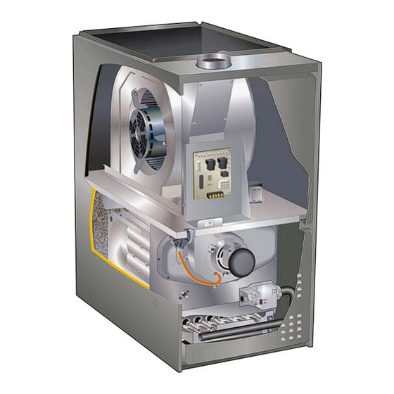
ML180DF PARTS ARRANGEMENT Secondary Limit Blower Assembly Flue Chase Control Box (includes integrated control, interlock switch and transformer) Blower Access Panel Heat Exchanger Combustion Air Inducer Primary Limit (under combustion air inducer) Gas Valve Burner Box (includes sensor, ignitor Heating Compartment and rollout switches) Access Panel FIGURE 1... -
Page 6: I Unit Components
I-UNIT COMPONENTS 3. Integrated Control (A92) ML180DF unit components are shown in figure 1.The gas WARNING valve, combustion air inducer and burners can be ac cessed by removing the heating compartment access pan Shock hazard. el. Electrical components are in the control box (figure 2) Disconnect power before servicing. - Page 7 TABLE 1 TABLE 2 4-Pin Terminal Designation 12-Pin Terminal Designations PIN # FUNCTION PIN # FUNCTION Combustion Air Inducer Line High Limit Output Ignitor Line Sensor 24V Line Combustion Air Inducer Neutral Not Used Ignitor Neutral Rollout Switch Out 24V Neutral High Limit Input Ground Gas Valve Common...
- Page 8 TABLE 3 Fan Time Control Heating Fan On Time Note - This control is equipped with a push button switch for The fan on time of 30 seconds is not adjustable. diagnostic code recall. The control stores the last 5 fault Heating Fan Off Time codes in non-volatile memory.
- Page 9 The switch is factory set and cannot be ad justed. The switch may have a different setpoint for each unit model number. If limit switch must be replaced, refer to Len nox ProductZone repair parts list on Lennox DaveNet®. Page 9...
- Page 10 To Measure Flame Signal - Integrated Control: 6 - Turn supply voltage on and close thermostat contacts to cycle system. Use a digital readout meter capable of reading DC micro 7 - When main burners are in operation for two minutes, take amps.
- Page 11 7. Ignitor (Figure 6) NOTE - The ML180DF furnace contains electronic The nitride ignitor used on ML180DF units is made from a components that are polarity sensitive. Make sure that proprietary ceramic material. To check ignitor, measure its the furnace is wired correctly and is properly grounded. resistance and voltage.
- Page 12 The purpose of the LPG changeover kits are available from Lennox. Kits include switch is to prevent burner operation if the combustion air in burner orifices and a gas valve regulator spring.
- Page 13 Remove tubing from CAI and insert “Tee” and additional tubing. MULTI−METER SET TO MEASURE OHMS Pressure Switch Field Provided Tubing To CAI Port High FIGURE 9 11. Blower Motors and Capacitors Supply Air Blower All ML180DF units use direct drive blower motors. All motors are 120V permanent split capacitor motors to ensure maxi...
-
Page 14: Iii Start Up
II- PLACEMENT AND INSTALLATION 2 - Turn off all electrical power to the unit if service is to be performed. Make sure unit is installed in accordance with installation 3 - Remove the heating compartment access panel. instructions and applicable codes. 4 - Move gas valve switch to OFF position. - Page 15 Flame should be stable and should not lift from Gas Leak Detector is strongly recommended. It is available burner. Natural gas should burn blue. through Lennox under part number 31B2001. See Corp. 4 - After allowing unit to stabilize for 5 minutes, record 8411-L10, for further details.
- Page 16 TABLE 9 Manifold Pressure Settings at all Altitudes Supply Pressure Model in.wg. 0-4500 ft 4501-7500 ft 7501 - 10,000 ft Input Size 13.0 LP/propane 10.0 10.0 10.0 11.0 13.0 13.0 LP/propane 10.0 10.0 10.0 11.0 13.0 13.0 LP/propane 10.0 10.0 10.0 11.0 13.0...
- Page 17 H- Proper Ground and Voltage CHECK VOLTAGE BETWEEN LINE HOT A poorly grounded furnace can contribute to premature ig AND LINE NEUTRAL nitor failure. Use the following procedure to check for ground and voltage to the integrated control. 1 - Measure the AC voltage between Line Neutral (spade terminals) and “C”...
- Page 18 V-TYPICAL OPERATING CHARACTERISTICS C-External Static Pressure 1 - Tap locations shown in figure 16 . A-Blower Operation and Adjustment 2 - Punch a 1/4” diameter hole in supply and return air ple NOTE- The following is a generalized procedure and nums.
-
Page 19: Vi Maintenance
Remove any blockage. Figure specifications provided by the filter manufacturer 17 shows burner detail. against the data given in the appropriate Lennox 12- To clean the combustion air inducer visually inspect and Product Specifications bulletin. Additional informa... - Page 20 ML180DF BURNER, COMBUSTION AIR INDUCER ASSEMBLY & HEAT EXCHANGER REMOVAL Internal flue pipe Gasket Gasket Glue chase Orifice plate Heat exchanger Pressure switch Nox insert (if applicable) Collector box Burner box assembly Combustion air inducer Ignitor Burners Sensor Retention rings Manifold and Gas valve Rollout...
- Page 21 C-Supply Air Blower 1 - Check and clean blower wheel. 2 - Motors used on the Lennox ML180DF series units are permanently lubricated and need no further lu Check Motor AMP Draw brication. (upflow furnace shown) D-Flue and Chimney Flue must conform to local codes. In the absence of local codes, flue must meet the National Fuel Gas Code ANSI-Z223.1 venting requirements.
-
Page 22: Vii Wiring And Sequence Of Operation
VII- WIRING AND SEQUENCE OF OPERATION ML180DF Schematic Wiring Diagram and Sequence of Operation Line voltage is applied to L1 and N. the T1 low voltage transformer is energized, and line voltage is applied to B3 indoor blower. S47 rollout switch must be closed in order for 24V from transformer to be output on integrated control ”R” to power thermostat. When there is a call for heat, W1 of the thermostat energizes W of the furnace control with 24VAC. -
Page 23: Heating Sequence Of Operation
Troubleshooting: Heating Sequence of Operation HEATING SEQUENCE OF OPERATION ABNORMAL HEATING MODE NORMAL HEATING MODE POWER ON GAS VALVE OFF. COMBUSTION AIR INDUCER OFF. INDOOR BLOWER DELAY OFF. CONTROL SELF-CHECK OKAY? LED: OFF POLARITY REVERSED. IS POLARITY CORRECT? LED: 9 FLASHES IMPROPER GROUND. - Page 24 Troubleshooting: Heating Sequence of Operation (Continued) HEATING SEQUENCE CONTINUED NORMAL HEATING MODE ABNORMAL HEATING MODE 15‐SECOND COMBUSTION AIR INDUCER PREPURGE INITIATED BY CLOSED PRESSURE SWITCH. LED: ON STEADY UNTIL VOLTAGE IS IS VOLTAGE ABOVE 90 VOLTS? ABOVE 95 VOLTS, IGNITOR WARM‐UP -- 20 SECONDS. THEN RESTARTS HEATING SEQUENCE.
-
Page 25: Troubleshooting: Cooling Sequence Of Operation
Troubleshooting: Cooling Sequence of Operation COOLING SEQUENCE OF OPERATION NORMAL COOLING MODE ABNORMAL COOLING MODE POWER ON IGNITION CONTROL MAIN POWER ON. LED: ON STEADY GAS VALVE OFF. COMBUSTION AIR INDUCER OFF. INDOOR BLOWER OFF WITH NORMAL DELAY. CONTROL SELF DIAGNOSTIC CHECK. LED: OFF IS CONTROL OPERATING NORMALLY? INTERRUPT MAIN POWER TO RESET CONTROL. - Page 26 Troubleshooting: Continuous Fan Sequence of Operation CONTINUOUS FAN SEQUENCE OF OPERATION LED: ON STEADY MANUAL FAN SELECTION MADE AT THERMOSTAT. CONTROL (G) ENERGIZES SYSTEM FAN ON CONTINUOUS BLOWER SPEED. EAC TERMINAL IS ENERGIZED. HUM TERM. ENERGIZES THERMOSTAT CALLS FOR HEAT (W). WITH COMB.
-
Page 27: Viii Twinning
VIII- TWINNING Twinning 2 ML180DF Furnaces between the ”C” and ”Twin” terminals of the two controls. The 24 VAC secondary of the two systems must be in The control board in this furnace is equipped with a provi phase. All thermostat connections are made to one control sion to ”twin”...
Need help?
Do you have a question about the ML180DF045P24A and is the answer not in the manual?
Questions and answers