
Related Manuals for Aertesi ECOELEGANT SERIES


Summary of Contents for Aertesi ECOELEGANT SERIES
- Page 1 ECOELEGANT SERIES INSTALLATION AND OPERATION MANUAL HWN-EC SERIES AERTESI srl Via della tecnica 6 35020 Conselve- PD ITALY www.aertesi.com NA version 2.1 Revised: Feb. 17, 2014 AER.MIU.HWNEC.GB.01.04/14...
- Page 2 Page 2 of 36 INVESTING IN QUALITY, RELIABILITY & PERFORMANCE. ISO 9001 QUALITY World Leading Design and Technology Every product is manufactured to meet Equipped with the latest CAD/CAM computer aided stringent requirements design and manufacturing technology, our factories in internationally recognized 9001...
-
Page 3: Table Of Contents
Page 3 of 36 Table of Content TECHNICAL DATA ........................4 A.1........................4 ENERAL ESCRIPTION A.2........................5 ENERAL PECIFICATION A.2.1. HWN–EC Series 3-Speed Specifications ....................5 A.3........................7 IMENSIONAL RAWINGS SERVICE AND INSTALLATION ....................7 B.1....................... 7 NSTALLATION OF B.1.1. -
Page 4: Technical Data
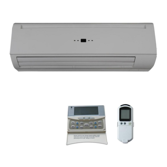
Page 4 of 36 Technical Data A.1. General Description This High-Wall Unit is designed to meet and exceed demanding requirements for efficiency, quiet operation and appearance. The sleek profile and elegantly styled cabinet complements any interior design theme, while the microprocessor assures accurate environmental control. -
Page 5: General Specification
Page 5 of 36 A.2. General Specification A.2.1. HWN–EC Series 3-Speed Specifications Product range: HWN-EC Hydronic High Wall with EC Motor HWN-EC Hydronic High Wall 2-pipe with EC Motor HWN-EC N.A. N.A. Configuration 2-pipe Number Of Fan Blowers Single 230/1/50 Power Supply (V/Ph/Hz) 220/1/60... - Page 6 Page 6 of 36 Product range: HWS-EC Hydronic High Wall with EC Motor HWN-EC N.A. N.A. Configuration 2-pipe Number Of Fan Blowers Single 230/1/50 Power Supply (V/Ph/Hz) 220/1/60 ~S: Complete function onboard PCB with integrated group control functionality, incl. 1 pc return air sensor and 2 pcs temperature sensors.
-
Page 7: Dimensional Drawings
Page 7 of 36 A.3. Dimensional Drawings Dimensional drawing for HWN-25/30/40 -EC (All dimensions shown in mm) Information Service and Installation B.1. Installation of High-Wall Unit B.1.1. Selecting a Location Select the location for the High-wall unit with the following considerations in mind: The front of the air inlet and outlet should be clear of any obstructions. -
Page 8: Mounting Plate Dimensions
Page 8 of 36 The signal receiver on the unit must be kept away from any high frequency emission source. Keep the unit away from fluorescent lamps, which may affect the control system. To avoid electromagnetic control system interference, ensure control wires are installed separately from 220-240 VAC power wires. -
Page 9: Drilling The Condensate Drainage Hole
Page 9 of 36 B.1.4. Drilling the Condensate Drainage Hole 1. Ensure that the hole for condensate drainage is correctly positioned. The height should be lower than the bottom edge of the indoor unit. 2. Drill a 65mm diameter hole with a descending slope. 3. -
Page 10: Unit Maintenances And Preparations
Page 10 of 36 If the attached drain hose passes through an indoor area, insulate it with heat insulation material. B.2. Unit Maintenances and Preparations B.2.1. Opening and Closing Of Lift-Up Grille Cover Close the grille cover by pressing down at the Open the grille cover by lifting from the positions indicated by the arrows. -
Page 11: Air Purging
Page 11 of 36 B.2.3. Air Purging After connecting the water inlet and outlet pipes to the main supply lines turn on the main breaker and operate the unit in COOLING mode. Open the water inlet valve and flood the coil. Check all connections for water leakage. - Page 12 Page 12 of 36 Code 2-Pipe 4-Pipe Return air sensor Return air temperature (Tr) Chilled / hot water coil Chilled water coil circuit 2-pipe coil circuit sensor Analogue Input circuit (Ti1) (Ti1) Hot water coil circuit Hot water sensor (Ti2) Digital communication port to LED display / IR receiver LED display / IR receiver X-DIS1...
-
Page 13: Wiring Diagram Ebwpcgh-Ec
Page 13 of 36 C.1.3. Wiring Diagram EBWPCGH-EC SK2014-SON-002-TechMnl-SWC-003... -
Page 14: Configuration Settings
Page 14 of 36 C.1.4. Configuration Settings There are 2 DIP switches set on the PCB: a) DIPA-S1 (8 positions) SW1 – SW6: used for master-slave / BMS network address. SW7 – SW8: used for operating mode configuration. b) DIPB-S2 (6 positions) SW1: Occupancy / economy mode selection. -
Page 15: Control Logics For 2-Pipe System
Page 15 of 36 5. Mode configuration: DIPA-S1 Model Model setting Cool-Heat Cool-Heat + booster heater Cooling only Cool + primary heater 6. Unit ON/OFF There are 3 ways to turn the system on or off: a) By the ON/OFF button on the handset or wired wall pad. b) By the programmable timer on the handset or wired wall pad. - Page 16 Page 16 of 36 a) MTV2, AUX2 and electric heater are always off. b) If Tr ≤ Ts - 1 ºC (or - 4ºC if economy contact is activated), then heat operation is activated and MTV1 and AUX1 are turned on. Indoor fan runs at the set speed. c) If Tr >...
-
Page 17: Control Logics For 4-Pipe System
Page 17 of 36 f) When the unit is turned off, indoor fan shut down after 5 seconds. LOW TEMPERATURE PROTECTION OF INDOOR COIL a) If Ti1 ≤ 2ºC for 2 minutes, AUX2 is turned off. If low speed is selected via user interface, indoor fan runs at medium speed. - Page 18 Page 18 of 36 b) If Tr ≥ Ts + 1ºC (or + 4ºC if economy contact is activated), then cool operation is activated, MTV1 and AUX2 are turned on. Indoor fan runs at set speed. c) If Tr < Ts, then cool operation is terminated, MTV1 and AUX2 are turned off. Indoor fan runs at set speed. d) The range of Ts is 16 - 30ºC e) Indoor fan speed can be adjusted to low, medium, high and auto.
-
Page 19: Auto Fan Speed
Page 19 of 36 a) MTV2, AUX1 and heater are always off. b) If Tr ≥ 25ºC, then MTV1 and AUX2 will be turned on for 3 minutes, and then off for 4 minutes. c) If 16ºC ≤ Tr < 25ºC, then MTV1 and AUX2 will be turned on for 3 minutes, and then off for 6 minutes. d) If Tr <16ºC, then MTV1 and AUX2 will be turned off for 4 minutes. -
Page 20: C.1.11. Operation Of Control Panel On High-Wall Unit
Page 20 of 36 The system uses non-volatile memory to save the present operation parameters when system is turned off or in case of system failure or cessation of power supply. Operation parameters when using a handset are Mode, Set Temperature, Swing, and Fan Speed. When using a wall pad the parameters are Mode, Set Temperature, Swing, and Fan Speed, as well as the 7-day ON/OFF Timer program. -
Page 21: Led Lights
Page 21 of 36 C.2. LED Lights For all units Power / Operation LED light (both green) Unit on Operation LED On, Power LED Off Unit in standby Power LED On, Operation LED Off C.2.1. LED Indication and Error Description For all units - Operation LED light (Green) Error Description Blink... -
Page 22: Led Indication On Master/Slave Connection
Page 22 of 36 C.2.2. LED Indication on Master/Slave Connection For master unit indicating defect status of all slave units. Error message can be found in LED lights on master unit. Master unit Protection LED light (Red) Unit No. Blink Remedy Unit 2 failure RED LED blinks 2 times, stops for 3 secs... -
Page 23: C.3.2. Master - Slave Network Setup
Page 23 of 36 The slave units can be set individually for timer ON/OFF function by handset or wall pad. The handset cannot override the wall pad timer and clock setting. C.3.2. Master – Slave Network Setup 1) Disconnect the communication plug from the SK-NCSWC-001 2) Communication plug A, B, A, B is printed on the main PCB. -
Page 24: Master-Slave Communication Method
Page 24 of 36 3.3.2) Check the wire contact by using a multimeter. contact contact contact contact contact contact 3.3.3) Check 1 and 2, 3 and 4, 5 and 6 to be sure the connections are correct. 3.3.4) If the resistance between two wire contacts is too high, please check and reconnect the wire contacts. 4) Reconnect the communication plug to the control box Using Remote Control Handset to Set Master Control Unit: a) Connect all the units PCBs according to the wire color and type of connector. - Page 25 Page 25 of 36 The Master unit will broadcast the settings to all slave units. During normal operation, slave units can receive commands from its local wireless handset and wall pad control panel. Upon reception of master global commands, all slave unit settings will be replaced by the master settings. Addressable communication The Master controller must be the LCD wall pad.
-
Page 26: Unit Network Wiring Scheme
Page 26 of 36 C.3.4. Unit Network Wiring Scheme Wiring diagram for a master-slave network connection SK2014-SON-002-TechMnl-SWC-003... -
Page 27: Sk-Ncswc-002 Limited Function Fcu Controller (On Demand)
Page 27 of 36 C.4. SK-NCSWC-002 Limited function FCU Controller (ON DEMAND) Used in all High-wall [V/P] ~W unit configurations. Ti1 = Chilled water coil temperature (10K) C.4.1. Definition of Input/Output Code 2-Pipe Analogue Input Chilled water sensor Coil sensor Power input 230 Voltage input (NO). -
Page 28: Wiring Diagram Sk-Ncswc-002
Page 28 of 36 C.4.2. Wiring Diagram SK-NCSWC-002 SK2014-SON-002-TechMnl-SWC-003... -
Page 29: Onboard Configuration
Page 29 of 36 C.4.3. Onboard Configuration There is 1 DIP switch set on the PCB: DIPB (4 positions) SW1: configured for different modulating signal SW2 – SW4: brushless DC fan motor configuration. Code State Description PCB configured for 0~5VDC modulating signal input. PCB configured for 0~10VDC modulating signal input. -
Page 30: Led Indication
Page 30 of 36 C.4.5. LED Indication For all units Power / Operation LED light (both green) Unit on Operation LED On, Power LED Off Unit in standby Power LED On, Operation LED Off C.4.6. Error Description For all units - Operation LED light (Green) Item Blink Reason... -
Page 31: User Interface
Page 31 of 36 User Interface D.1. Remote Control Handset Attention When unit with handset is the master unit, settings are automatically sent to the slave units; Auto Cool-Heat operation will be applicable in 4-pipe system only. “Swing” function is not applicable. SK2014-SON-002-TechMnl-SWC-003... -
Page 32: Wired Wall Pad
Page 32 of 36 D.2. Wired Wall Pad D.2.1. Wall Pad Display SK2014-SON-002-TechMnl-SWC-003... -
Page 33: Wall Pad Operation Guidelines
Page 33 of 36 D.2.2. Wall Pad Operation Guidelines Clock display and setting System has an accurate internal real time clock used for time indication and timer ON/OFF function. Clock display area TI M E TI M E indicates internal time clock which can be set by the button. - Page 34 Page 34 of 36 TI M ER Upon completion of changing timer settings for the selected day, press button again to exit timer programming mode. The settings will then upload to the selected slave unit. The next day of the week’s settings can be done only upon completion of sending data to the slave units.
- Page 35 Page 35 of 36 C AN C EL Hold down buttons for 3 seconds to enter into operation parameters browsing mode. Unit’s display area shows the address of the slave unit being viewed. Slave unit selection method is the same as in networking control above. Press to browse various parameters as follow: Wall pad display temperature area...
-
Page 36: Troubleshooting Guide
Page 36 of 36 Troubleshooting Guide Symptoms Cause Remedy The fan coil does - Check for presence of No voltage not start up voltage - Check fuse on board Mains switch in the “OFF - Place in the “ON” position position Faulty room control - Check the room control...
Need help?
Do you have a question about the ECOELEGANT SERIES and is the answer not in the manual?
Questions and answers