Table of Contents
Advertisement
SPLIT-TYPE AIR CONDITIONERS
INDOOR UNIT
SERVICE MANUAL
Models
MSZ-HE09NA
MSZ-HE12NA
MSZ-HE15NA
MSZ-HE18NA
MSZ-HE24NA
NOTE:
RoHS compliant products have <G> mark on the spec name plate.
Outdoor unit service manual
MUZ-HE•NA Series (OBH686)
CONTENTS
2. PART NAMES AND FUNCTIONS ····················· 3
3. SPECIFICATION ················································ 5
4. OUTLINES AND DIMENSIONS ························ 7
5. WIRING DIAGRAM ············································ 8
6. REFRIGERANT SYSTEM DIAGRAM ··············· 9
7. SERVICE FUNCTIONS ··································· 10
8. MICROPROCESSOR CONTROL ··················· 12
9. TROUBLESHOOTING ····································· 16
10. DISASSEMBLY INSTRUCTIONS ···················· 32
PARTS CATALOG (OBB685)
No. OBH685
2
·······································
Advertisement
Table of Contents
Troubleshooting

Subscribe to Our Youtube Channel
Related Manuals for Mitsubishi Electric MSZ-HE09NA


Summary of Contents for Mitsubishi Electric MSZ-HE09NA
-
Page 1: Table Of Contents
SPLIT-TYPE AIR CONDITIONERS INDOOR UNIT No. OBH685 SERVICE MANUAL Models MSZ-HE09NA MSZ-HE12NA MSZ-HE15NA MSZ-HE18NA MSZ-HE24NA Outdoor unit service manual MUZ-HE•NA Series (OBH686) CONTENTS 1. TECHNICAL CHANGES ······································· 2. PART NAMES AND FUNCTIONS ····················· 3 3. SPECIFICATION ················································ 5 4. OUTLINES AND DIMENSIONS ························ 7 5. -
Page 2: Technical Changes
Correct refrigerant is specified in the manuals and on the spec labels provided with our products. We will not be held responsible for mechanical failure, system malfunction, unit breakdown or accidents caused by failure to follow the instructions. TECHNICAL CHANGES MSZ-HE09NA MSZ-HE12NA MSZ-HE15NA MSZ-HE18NA MSZ-HE24NA 1. -
Page 3: Msz-He09Na Msz-He12Na Msz-He15Na Msz-He18Na
PART NAMES AND FUNCTIONS MSZ-HE09NA MSZ-HE12NA MSZ-HE15NA MSZ-HE18NA Air filter Front panel Air cleaning filter (Anti-Allergy Enzyme Filter, optioin) Air inlet Heat exchanger Remote controller Air outlet Horizontal vane Display section Remote control receiving section Operation indicator lamp Emergency operation switch (E.O. SW) - Page 4 MSZ-HE24NA Front panel Air filter Air cleaning filter (Electrostatic anti-allergy enzyme filter, option) Air inlet Air outlet Remote controller Heat exchanger Horizontal vane Display section ACCESSORIES Model MSZ-HE09/12/15/18NA MSZ-HE24NA Installation plate Attachment screws for the installation plate 4 × 25 mm Battery (AAA) for the remote controller Wireless remote controller Felt tape (For left or left-rear piping)
-
Page 5: Specification
SPECIFICATION Indoor model MSZ-HE09NA MSZ-HE12NA Power supply V, phase, Hz 208/230, 1, 60 Max. fuse size (time delay)/ Disconnect switch A Min. circuit ampacity Fan motor F.L.A 0.76 COOL Dry 399-321-237-170 Airfl ow (Wet) (364-286-201-134) Super High - High - Med. -... - Page 6 1 ft./s., (CFM) (ft./s.) when air is blown out horizontally from HEAT 20.6 29.5 the unit properly at the High speed posi- MSZ-HE09NA 16.3 23.5 tion. COOL 14.5 21.0 The coverage should be used only as a...
-
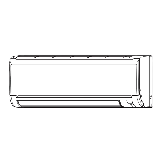
Page 7: Outlines And Dimensions
OUTLINES AND DIMENSIONS MSZ-HE09NA MSZ-HE12NA MSZ-HE15NA MSZ-HE18NA Unit: inch 7/16×13/16 Oblong hole 7/16×1 Oblong hole 8-7/8 8-7/8 3-1/8 3-1/8 Installation plate 31-7/16 30-15/16 6-1/8 6-1/8 2-3/8 13-5/16 13-9/16 2-1/8 Air in Wall hole ø2-9/16 9-1/8 Indoor unit 3/16 Installation plate... -
Page 8: Wiring Diagram
WIRING DIAGRAM MSZ-HE09NA MSZ-HE12NA MSZ-HE15NA MSZ-HE18NA MSZ-HE24NA OBH685... -
Page 9: Refrigerant System Diagram
REFRIGERANT SYSTEM DIAGRAM MSZ-HE09NA MSZ-HE12NA MSZ-HE15NA MSZ-HE18NA Unit: inch Refrigerant pipe ø3/8 (MSZ-HE09/12NA) ø1/2 (MSZ-HE15/18NA) (with heat insulator) Indoor coil Indoor thermistor heat RT12 (main) exchanger Flared connection Indoor coil thermistor RT13 (sub) Room temperature thermistor RT11 Flared connection Refrigerant pipe ø1/4... -
Page 10: Service Functions
SERVICE FUNCTIONS MSZ-HE09NA MSZ-HE12NA MSZ-HE15NA MSZ-HE18NA MSZ-HE24NA 7-1. TIMER SHORT MODE For service, the following set time can be shortened by bridging JPG and JPS on the indoor electronic control P.C. board. (Refer to 9-7.) • The set time for the ON/OFF timer can be reduced to 1 second for each minute. - Page 11 7-3. AUTO RESTART FUNCTION When the indoor unit is controlled with the remote controller, the operation mode, the set temperature, and the fan speed are memorized by the indoor electronic control P.C. board. “AUTO RESTART FUNCTION” automatically starts operation in the same mode just before the shut-off of the main power. Operation If the main power has been cut, the operation settings remain.
-
Page 12: Microprocessor Control
MICROPROCESSOR CONTROL MSZ-HE09NA MSZ-HE12NA MSZ-HE15NA MSZ-HE18NA MSZ-HE24NA WIRELESS REMOTE CONTROLLER Signal transmitting section Operation display section ON/OFF (operate/stop) button Fan speed control button Temperature buttons ECONO COOL button Vane control button Operation select button Timer mode select button Time set buttons RESET button NOTE: Last setting will be stored after the unit is turned OFF with the remote controller. - Page 13 8-2. DRY ( ) OPERATION (1) Press OPERATE/STOP (ON/OFF) button. OPERATION INDICATOR lamp of the indoor unit turns ON with a beep tone. (2) Select DRY mode with OPERATION SELECT button. (3) The set temperature is determined from the initial room temperature. 1.
- Page 14 (5) STOP (operation OFF) and ON TIMER standby In the following cases, the horizontal vane returns to the closed position. (a) When OPERATE/STOP (ON/OFF) button is pressed (POWER OFF). (b) When the operation is stopped by the emergency operation. (c) When ON TIMER is ON standby. (6) Dew prevention During COOL or DRY operation with the vane angle at Angle 4 or 5 when the compressor cumulative operation time exceeds 1 hour, the vane angle automatically changes to Angle 1 for dew prevention.
- Page 15 8-6. EMERGENCY/TEST OPERATION In the case of test run operation or emergency operation, use EMERGENCY OPERATION switch on the right side of the indoor unit. Emergency operation is available when the remote controller Operation mode COOL HEAT is missing or has failed, or when the batteries in the remote controller are Set temperature 75°F(24°C) 75°F(24°C)
-
Page 16: Troubleshooting
TROUBLESHOOTING MSZ-HE09NA MSZ-HE12NA MSZ-HE15NA MSZ-HE18NA MSZ-HE24NA 9-1. CAUTIONS ON TROUBLESHOOTING 1. Before troubleshooting, check the following 1) Check the power supply voltage. 2) Check the indoor/outdoor connecting wire for miswiring. 2. Take care of the following during servicing 1) Before servicing the air conditioner, be sure to turn OFF the unit first with the remote controller, and then after confirm- ing the horizontal vane is closed, turn OFF the breaker and/or disconnect the power plug. -
Page 17: Failure Mode Recall Function
9-2. FAILURE MODE RECALL FUNCTION Outline of the function This air conditioner can memorize the abnormal condition which has occurred once. Even though LED indication listed on the troubleshooting check table (9-4.) disappears, the memorized failure details can be recalled. 1. - Page 18 2. Indoor unit failure mode table Upper lamp of OP- Abnormal point ERATION INDICA- Condition Remedy (Failure mode) TOR lamp Not lighted Normal — — The room temperature thermistor short or 1-time fl ash every Room temperature Refer to the characteristics of the room temperature open circuit is detected every 8 seconds dur- 0.5-second thermistor...
- Page 19 9-3. INSTRUCTION OF TROUBLESHOOTING Start Indoor unit operates. Indoor unit does Indoor unit oper- OPERATION INDICATOR Outdoor unit does not receive the ates. lamp on the indoor unit is not operate normally. Outdoor unit signal from re- fl ashing ON and OFF. mote controller.
-
Page 20: Troubleshooting Check Table
9-4. TROUBLESHOOTING CHECK TABLE Before taking measures, make sure that the symptom reappears for accurate troubleshooting. When the indoor unit has started operation and detected an abnormality of the following condition (the first detection after the power ON), the indoor fan motor turns OFF and OPERATION INDICATOR lamp flashes. OPERATION INDICATOR Lighted Blinking... - Page 21 9-5. TROUBLE CRITERION OF MAIN PARTS MSZ-HE09NA MSZ-HE12NA MSZ-HE15NA MSZ-HE18NA MSZ-HE24NA Part name Check method and criterion Figure Measure the resistance with a tester. Room temperature thermistor (RT11) Refer to 9-7. "Test point diagram and voltage", 2 or 3. "Indoor electronic Indoor coil thermistor control P.C.
-
Page 22: Troubleshooting Flow
9-6. TROUBLESHOOTING FLOW A Check of indoor fan motor MSZ-HE09/12/15/18NA The indoor fan motor error has occurred, and the indoor fan does not operate. Turn OFF the power supply. Pay enough attention to the high voltage on the fan motor connector. Turn ON the power supply, wait 5 seconds or more, and then press EMERGENCY OPERATION switch. - Page 23 MSZ-HE24NA The indoor fan motor error has occurred, and the indoor fan does not operate. Turn OFF the power supply. Pay enough attention to the high voltage on the fan motor connector. Turn ON the power supply, wait 5 seconds or more, and then press EMERGENCY OPERATION switch.
- Page 24 B Check of remote controller and indoor electronic control P.C. board Check if the remote controller is exclusive for this air conditioner. MSZ-HE09/12/15/18NA Press OPERATE/STOP (ON/OFF) button on the remote controller. 1 Look at the image of the signal transmitting section of the remote controller through the monitor of a digital camera or a camera phone.
- Page 25 C Check of indoor P.C. board and indoor fan motor MSZ-HE09/12/15/18NA Turn OFF the power supply. Remove indoor fan motor connector CN211 from indoor power P.C. board and vane Measure the resistance of indoor fan Short circuit: motor connector CN151 from the indoor motor.
- Page 26 MSZ-HE24NA Turn OFF the power supply. Remove indoor fan motor connector CN211 and Short circuit: Measure the resistance between CN211 Replace the indoor fan motor. vane motor connector CN151 from the indoor electronic of the indoor fan motor connector. control P.C. board and turn ON the power supply. Does the unit operate with the remote controller? Short circuit: Measure the resistance of the horizontal vane...
- Page 27 D How to check miswiring and serial signal error MSZ-HE09/12/15/18NA Turn OFF the power supply. Is there rated voltage in the power supply? Check the power supply. Turn ON the power supply. Check the wiring. Is there rated voltage between outdoor terminal block S1 and S2? Press EMERGENCY OPERATION switch once.
- Page 28 MSZ-HE24NA Turn OFF the power supply. Is there rated voltage in the power supply? Check the power supply. Turn ON the power supply. Is there rated voltage between outdoor terminal block S1 and S2? Check the wiring. Press EMERGENCY OPERATION switch once. Does the OPERATION INDICATOR lamp light up? <Confi...
- Page 29 E Electromagnetic noise enters into TV sets or radios Is the unit grounded? Ground the unit. Is the distance between the antennas Extend the distance between the antennas and and the indoor unit within 9.91 ft. (3 m), the indoor unit, and/or the antennas and the or is the distance between the antennas outdoor unit.
- Page 30 9-7. TEST POINT DIAGRAM AND VOLTAGE 1. Indoor power P.C. board, Indoor terminal P.C. board MSZ-HE09NA MSZ-HE12NA MSZ-HE15NA MSZ-HE18NA Indoor terminal P.C. board Indoor power P.C. board Varistor (NR11) Resistor (R111) Fuse (F11)( ) Indoor fan motor (CN211) 294/325 VDC (–) GND (high-...
- Page 31 3. Indoor terminal P.C. board, Indoor electronic control P.C. board, Power monitor receiver SW P.C. board MSZ-HE24NA Indoor terminal P.C. board Indoor electronic control P.C. board Indoor coil thermistor To disable "Auto restart function", Fuse Terminal Varistor Resistor RT12, RT13 12 VDC solder the Jumper wire to JR07.
-
Page 32: Disassembly Instructions
Pull the terminal while pull out the terminal pushing the locking slowly. Locking lever lever. Connector 10-1. MSZ-HE09NA MSZ-HE12NA MSZ-HE15NA MSZ-HE18NA NOTE: Turn OFF power supply before disassembly. OPERATING PROCEDURE PHOTOS 1. Removing the panel Photo 1 (1) Remove the horizontal vanes. - Page 33 OPERATING PROCEDURE PHOTOS 2. Removing the indoor electronic control P.C. Photo 2 board and the room temperature thermistor Electrical box Ground wire (1) Remove the panel (Refer to 1.) and the corner box. (2) Remove the screw of the V.A. clamp and the V.A. clamp.
- Page 34 OPERATING PROCEDURE PHOTOS 4. Removing the nozzle assembly Photo 4 (1) Remove the panel (Refer to 1.) and the corner box. (2) Remove the indoor/outdoor connecting wire (Refer to 2 (2)-(5).). (3) Remove the indoor electronic control P.C. board hold- (4) Pull out the drain hose from the nozzle assembly and remove the nozzle assembly.
- Page 35 OPERATING PROCEDURE PHOTOS 6. Removing the indoor fan motor, the indoor coil Photo 5 thermistor, and the line flow fan (1) Remove the panel (Refer to 1.) and the corner box. (2) Remove the indoor electronic control P.C. board hold- er, the electrical box and the nozzle assembly.
- Page 36 10-2. MSZ-HE24NA NOTE: Turn OFF power supply before disassembly. OPERATING PROCEDURE PHOTOS 1. Removing the panel Photo 1 (1) Remove the horizontal vanes. Horizontal vanes Front panel (2) Remove the screw caps of the panel. Remove the screws of the panel. (3) Hold the lower part of both ends of the panel and pull it slightly toward you, and then remove the panel by pushing it upward.
- Page 37 OPERATING PROCEDURE PHOTOS 4. Removing the nozzle assembly Photo 4 (1) Remove the panel (Refer to 1.) and the corner box. (2) Remove the V.A. clamp, and then the indoor/outdoor connecting wire. (Refer to 2 (2)-(4).) (3) Remove the electrical cover. (Photo 2) (4) Disconnect the following connectors on the electronic control P.C.
- Page 38 OPERATING PROCEDURE PHOTOS 6. Removing the water cut, the indoor fan motor, Photo 6 the indoor coil thermistor, and the line flow fan (1) Remove the panel (Refer to 1.) and the corner box. (2) Remove the power monitor receiver holder, the electri- cal box and the nozzle assembly.
- Page 39 Fixing the indoor coil thermistor There are 2 forms of parts for fixing the indoor coil thermistor. When fixing the indoor coil thermistor to the clip-shape/holder-shape part, the Clip shape Holder shape lead wire should point down. About the same length Position and procedure for mounting the clip-shape part 1.
- Page 40 HEAD OFFICE: TOKYO BLDG., 2-7-3, MARUNOUCHI, CHIYODA-KU, TOKYO 100-8310, JAPAN © Copyright 2014 MITSUBISHI ELECTRIC CORPORATION Distributed in Feb. 2014. No. OBH685 New publication, effective Feb. 2014 Made in Japan Specifications are subject to change without notice.
Need help?
Do you have a question about the MSZ-HE09NA and is the answer not in the manual?
Questions and answers