Table of Contents
Advertisement
Note: This owner's manual for the Acoustic 450 has been reconstructed from digital scans of an
original manual, run through OCR software and reconstituted into a printable document. Every effort
has been made to retain the content integrity of the original document. Thanks Julien for the files.
OWNER'S MANUAL
control corporation
MODEL 450
LEAD / BASS AMPLIFIER
acoustic control corporation
7949 Woodley Avenue
Van Nuys, Ca. 91406
(213) 997-6631
1
P/N 410134
Advertisement
Table of Contents

Related Manuals for Acoustic 450


Summary of Contents for Acoustic 450
-
Page 1: Input
Note: This owner’s manual for the Acoustic 450 has been reconstructed from digital scans of an original manual, run through OCR software and reconstituted into a printable document. Every effort has been made to retain the content integrity of the original document. Thanks Julien for the files. -
Page 2: Input
A WORD TO ACOUSTIC AMPLIFIER OWNERS We would like to take this opportunity to thank you for choosing an ACOUSTIC product and to assure you of our continuing interest in your musical pleasure and satisfaction. This manual has been prepared to acquaint you with the proper operation of your amplifier and to provide important information as to its many capabilities. -
Page 3: Table Of Contents
TABLE OF CONTENTS Page ACOUSTIC LIFETIME WARRANTEE GENERAL DESCRIPTION MODEL 450 - SPECIAL FEATURES 1. Lead / Bass Selector Switch 2. Special Output Circuit Configuration 3. Auxiliary Volume Control 4. Use Outside the United States FRONT PANEL VIEW OPERATION OF CONTROLS and CONNECTIONS CONNECTIONS 1. -
Page 4: Acoustic Lifetime Warrantee
COMPLETED AND MAILED TO ACOUSTIC WITHIN 10 (TEN) DAYS FROM THE DATE OF PURCHASE. Acoustic Control Corporation will validate the Warranty and return it to you for your files. The card MUST be validated for your warranty to be in effect. -
Page 5: General Description
Besides having a quality sound and a powerful sound system, the Model 450 excels in flexibility due to its advanced engineering. -
Page 6: Model 450-Special Features
MODEL 450-SPECIAL FEATURES LEAD/BASS SELECTOR SWITCH The LEAD/BASS switch located on the front panel allows the amplifier to be used as either a lead guitar or a bass guitar amplifier. The amplifier in the LEAD switch position is a wide-band flat amplifier. -
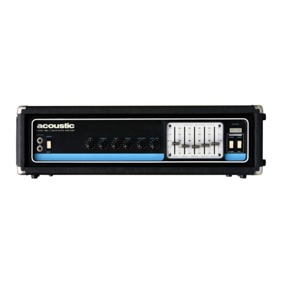
Page 7: Front Panel View
P/N 410134... -
Page 8: Operation Of Controls And Connections
OPERATION OF CONTROLS AND CONNECTIONS 1 & 2 INPUTS There are two input jacks on the left side of the front panel. The top input is louder than the bottom input. The top input should be used in most cases to achieve maximum signal-to-noise ratio. If your instrument puts out such a large signal that you can turn the volume control only slightly above the off position, then you should use the second input to cut down on the signal. -
Page 9: Distortion Control
OPERATION OF CONTROLS AND CONNECTIONS, continued 8 DISTORTION CONTROL This control is used to create a desired amount of distortion. Distortion is somewhat similar to the sound effect known as "fuzz." When the distortion control is turned fully counter clockwise, the distortion circuit is bypassed. -
Page 10: Graphic Equalizer
OPERATION OF CONTROLS AND CONNECTIONS, continued 13 GRAPHIC EQUALIZER The ACOUSTIC Graphic Equalizer is a unique device for musical instrument amplification similar in function to a studio equalizer. The Equalizer divides the guitar signal into five sections. Section 1 covers the 50 Hz to 110 Hz range;... -
Page 11: Rear Panel View
P/N 410134... -
Page 12: How To Use The Graphic Equalizer
16 BOOSTER OUTPUT This jack would be used if you desire to drive an additional power amplifier and speakers using the Model 450 head to control the extra amplifier. 17 LINE OUTPUT This jack is tied to the output of the preamplifier. As the volume is lowered, the output of this jack is lowered. -
Page 13: Accessory Jack
(See markings on the chassis.) 22 AC LINE CORD All Acoustic amplifiers have a three-conductor grounding system which connects the chassis ground to the line ground. This grounding system eliminates the possibility of shock hazard and hum pick-up. When Acoustic amplifiers are being used in conjunction with other equipment, make certain that the other equipment has this standard grounding scheme. -
Page 14: A Note On Speaker Impedances
A NOTE ON SPEAKER IMPEDANCES Any impedance between 2 ohms and 4 ohms will give optimum results; that is, 170 Watts RMS. 4 ohms is the best match because with a 4 ohm load, the amplifier runs slightly cooler. Low Impedances Use of impedances less than 2 ohms may reduce maximum power output and cause extraordinary heating. -
Page 15: Model 450 Physical Specifications
MODEL 450 PHYSICAL SPECIFICATIONS 1. CONNECTIONS Inputs 2 (1/4" phone jacks,2conductor) Speaker Outputs 2 (1/4" phone jacks, 2 conductor) Line Outputs 2 (1/4" phone jacks, 2 conductor) Booster Output 1 (1/4" phone jack, 2 conductor) In / Out Accessory 1 (1/4" phone jack, 3 conductor) Foot Switch Socket 1 (1/4"... -
Page 16: Model 450 Electrical Specifications
MODEL 450 ELECTRICAL SPECIFICATIONS 1. OUTPUT Power output (continuous) across 4 ohm load @ less than 5% distortion 170 Watts RMS Peak power output (instantaneous) across 4 ohm load @ 5% distortion 450 Watts Power output (continuous) across 2 ohm load... - Page 17 MODEL 450 ELECTRICAL SPECIFICATIONS, continued 6. AUXILIARY OUTPUTS Output Voltage 250 mv RMS Impedance 5000 ohms Booster Output 275mv RMS Impedance 1 K ohms 7. DISTORTION CIRCUIT (all controls flat, distortion control and volume control max.) Minimum Input Required to Clip Power Amp 425 Microvolts 8.
-
Page 18: Amplifier Line Voltage Requirements
AMPLIFIER LINE VOLTAGE REQUIREMENTS FOR OPERATION IN U.S.A. AND FOREIGN COUNTRIES 1. 107 Volts Line Used when supply line is 100V - 50/60 Hz Use 5A, 125V Slo-Blo Fuse as in Japan or Used when supply line is rated 110V CAUTION: Do not use 107V tap with 120V line 2. - Page 19 P/N 410134...
- Page 20 P/N 410134...
- Page 21 SPECIFICATION PART NO. 410173 SPEAKER CABINET SPECIFICATIONS ACOUSTIC MODEL 406 Speaker Complement 2 - 15" Cabinet Design bass reflex Cabinet Construction 3/4" plywood Speaker Access Front Cabinet Size 43" H X 18" D X 241/2" W Shipping Weight 130 lbs.
Need help?
Do you have a question about the 450 and is the answer not in the manual?
Questions and answers