Table of Contents
Advertisement
Quick Links
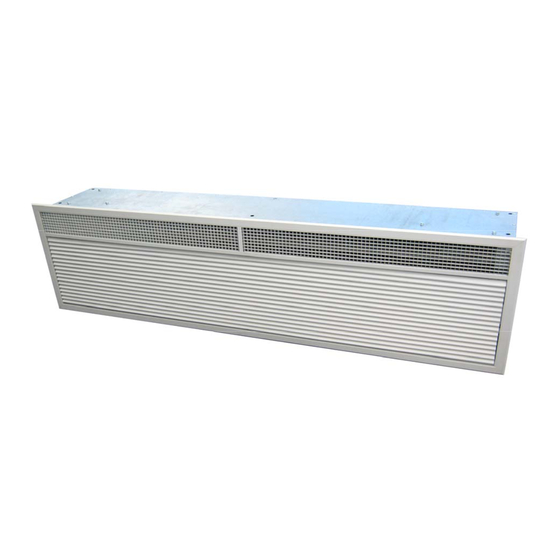
VRF HP RECESSED HEAT PUMP RANGE AIR CURTAINS
INSTALLATION, OPERATION & MAINTENANCE INSTRUCTIONS
For use with City Multi (VRF) systems
PLEASE READ THESE INSTRUCTIONS CAREFULLY BEFORE ATTEMPTING INSTALLATION
Thermoscreens Ltd
St. Mary's Road Nuneaton
Warwickshire England
CV11 5AU
English
Email:
sales@thermoscreens.com
Tel: +44 (0) 24 7638 4646
Fax: +44 (0) 24 7638 8578
www.thermoscreens.com
T9901078-1 UK
Page 1 of 36
Advertisement
Table of Contents

Related Manuals for Thermoscreens Air curtain system


Summary of Contents for Thermoscreens Air curtain system
- Page 1 VRF HP RECESSED HEAT PUMP RANGE AIR CURTAINS INSTALLATION, OPERATION & MAINTENANCE INSTRUCTIONS For use with City Multi (VRF) systems PLEASE READ THESE INSTRUCTIONS CAREFULLY BEFORE ATTEMPTING INSTALLATION Thermoscreens Ltd St. Mary’s Road Nuneaton Warwickshire England CV11 5AU English Email: sales@thermoscreens.com...
-
Page 2: Table Of Contents
Thermoscreens / Mitsubishi Electric City Multi (VRF) HP Recessed Heat Pump Air Curtain System CONTENTS Page Air Curtain System Schematics Design Information Unpacking the Air Curtain INSTALLATION Installation of the Air Curtain Figure 1 – Dimensions of VRF HP R Air Curtain... -
Page 3: Air Curtain System Schematics
The City Multi Y Series Heat Pump Air Curtain system consists of :- one or more Thermoscreens VRF HP Heat Pump (heating and cooling) Air Curtains * one or more Mitsubishi Electric City Multi Y/WY-Series Compressor Units ... - Page 4 The City Multi R2/WR2-Series heat recovery system with Heat Pump Air Curtain(s) consists of :- one or more Thermoscreens VRF HP Heat Pump (heating and cooling) Air Curtains * one or more Mitsubishi Electric City Multi R2/WR2-Series Compressor Units ...
-
Page 5: Design Information
(see separate Mitsubishi Electric Instructions). There is a Mitsubishi Electric M-Net communications link between the Mitsubishi Electric Compressor Unit or BC Controller and the Thermoscreens Heat Pump Air Curtain. When used with a Mitsubishi PAR-30MAA or PAR-27MEA Remote Controller this link provides:- ... - Page 6 Tests at the Building Research Establishment (BRE) test house on the heat pump air curtain system showed that even with the auxiliary heater cutting in during defrost, as it has to during their EN14511 performance test, the annual seasonal COP was hardly affected.
- Page 7 The air curtain is designed only for use with a Mitsubishi Electric City Multi (VRF) system for use on R410A. The complete Thermoscreens air curtain / Mitsubishi Electric heat pump system, including fridge pipework, wiring, controls, etc. must be installed only by an approved Mitsubishi Electric refrigeration contractor.
-
Page 8: Unpacking The Air Curtain
UNPACKING THE AIR CURTAIN The following items are supplied and packaged within the air curtain box :- Recessed Grille with Filter VRF Recessed Heat Pump Air Curtain Air Inlet Air Inlet Air Discharge Air Discharge If anything is missing or damaged please contact your place of purchase immediately. There will also be a 'City Multi (VRF) heat pump system' supplied by Mitsubishi Electric. -
Page 9: Serial Number
The complete Thermoscreens air curtain / Mitsubishi Electric heat pump system, to provide a heat pump air curtain over a doorway, including wiring, fridge pipework, etc. is to be installed only by an approved Mitsubishi Electric refrigeration contractor. IMPORTANT This Heat Pump Air Curtain is intended only for use with a Mitsubishi Electric City Multi (VRF) system, for use on R410A. -
Page 10: Installation Of The Air Curtain
INSTALLATION OF THE HEAT PUMP AIR CURTAIN The air curtain is designed to be recessed within ceiling voids or bulkheads within a building and located horizontally over a doorway. It must not be installed outside of the building. Location The air curtain must be mounted so the recessed grille is located up to 3.8m maximum above floor level and Air Inlet as close to the doorway as possible. - Page 11 On the VRF HP1500R and VRF HP2000R units there is an additional hanging point located towards the middle of the unit for an M10 hanging rod and this must be used. Ensure each of the hanging rods is secured onto a suitable structure that can support the weight of the unit (see Table on Page 10).* Adjust the height of the unit on its hanging rods so the bottom surface of the casing goes 38mm up into the ceiling as shown in the diagram.
- Page 12 T9901078-1 UK Page 12 of 36...
-
Page 13: Fitting The Recessed Grille
Fitting the Recessed Grille The recessed grille consists of a metal frame, cellular discharge grille and hinged inlet grille with inlet air filter HP1500R & attached to it. There are 4 fixing points on the VRF HP2000R only HP1000R unit and 6 fixing points on the VRF HP1500R and VRF HP2000R units, see picture - arrows indicate the fixing points. -
Page 14: Mitsubishi Electric Compressor Unit
Mitsubishi Electric Compressor Unit See table below for the VRF System Index Size to be used together with performance data for the air curtain. Air Curtain Parameters Maximum Maximum Max. Air Maximum Effective Air Curtain system Heating Cooling Volume Noise Width of Index Size Output... -
Page 15: To Gain Access Inside The Air Curtain
For the City Multi (VRF) R2 and WR2 Series system, pipework from each air curtain must connect to one pair of ports on the Mitsubishi Electric BC Controller. Do not combine pipework from two or more air curtains together into one set of pipework and then connect this to one pair of ports. -
Page 16: Electrical Supply And Wiring To The Air Curtain
Electrical Supply and Wiring to the Air Curtain This must be carried out AFTER the connection of the refrigerant pipework. All electrical wiring and connections MUST be carried out by a competent qualified electrician in accordance with the latest edition of the IEE wiring regulations and/or local statutory regulations. - Page 17 2) If the defrost cycle auxiliary heater is to be enabled during site commissioning, see Wiring Diagram 2, Page 19 (400V/3ph/50Hz electrical supply from separate local isolator) Connect to terminals Earth, L1, L2, L3 and N with a 3- phase electrical supply. Connect a Mitsubishi Electric PAR-30MAA Remote Controller to terminals 1 and 2 on the air curtain, or a PAR-F27MEA to terminals M1 and M2.
-
Page 18: Wiring Diagram 1 (Defrost Cycle Auxiliary Heater Disabled - As Supplied)
230V Black rectangle indicates moveable head of dip switch T9901078-1 UK Page 18 of 36... -
Page 19: Wiring Diagram 2 (Defrost Cycle Auxiliary Heater Enabled On Site)
MOVE VIOLET NEUTRAL WIRE FROM TERMINAL 14NO TO TERMINAL A2 FOR DEFROST HEATER TO WORK 230V Black rectangle indicates moveable head of dip switch T9901078-1 UK Page 19 of 36... -
Page 20: Par-30Maa Remote Controller
If the air curtain is to be manually controlled by the end user a Mitsubishi Electric PAR-30MAA remote controller (not supplied by Thermoscreens) must be supplied and fitted by the installer. This is wired to terminals 1 and 2 on the air curtain using 2-core cable. Refer to the Mitsubishi Electric instructions that come with the PAR-30MAA remote controller for the installation and wiring of the controller. - Page 21 If it is not practical to gravity drain from the air curtain a suitable condensate pump (not supplied with the unit) can be supplied and fitted by the installer to remove condensate directly from the unit. The condensate pump must be of sufficient capacity (see Table below) and if located higher than the drain tray;...
-
Page 22: Air Curtain Checks
There is a Mitsubishi Electric Interface PCB located within the left hand end of the Thermoscreens Air Curtain. This provides control and communication between the Mitsubishi Electric City Multi system and the Air Curtain Indoor Unit. It is held in place by a fixing screw located at the bottom edge of the PCB, see picture. - Page 23 Check that the dip switches on the Interface PCB are set as shown in Wiring Diagram 1 or 2 on Pages 18 and 19. The SW2 Capacity Setting dip switch should be as follows: VRF HP1000R VRF HP1500R VRF HP2000R 3 4 5 6 3 4 5 6 3 4 5 6...
-
Page 24: Selecting The Fan Speeds Of The Air Curtain
Selecting the Fan Speeds of the Air Curtain The fan motor(s) in the air curtain is a 6-speed motor and fan speeds can be re-selected at commissioning to suit the installation, both to suit the outdoor environmental conditions and for indoor noise levels. As delivered, for the 3 fan speeds available from the PAR-30MAA or PAR-F27MEA remote controller:- the HIGH fan speed (black wire) is wired into motor tapping 1 (highest motor speed... - Page 25 The table below provides guidance as to how the fan speeds can be set. WARNING: There are two motors on the VRF HP2000R DXE model, make sure both motors are wired up in exactly the same way or the motors will overheat with possible damage. Motor Speed Recommended air Sound...
-
Page 26: Starting The Heat Pump System
Starting the Heat Pump System Carry out a final inspection to ensure that all wiring is in accordance with Wiring Diagram 1 on Page 18 or wiring Diagram 2 on Page 19 and that all connections have been properly made. Ensure that the refrigerant system is complete, there are no leaks and there is sufficient charge of refrigerant R410A. -
Page 27: Filter Dirty Indicator
curtain and it should run in this set-up with no further adjustments, automatically heating as required. If the target temperature is reached the air curtain fans will still operate but the air stream is then not heated (ambient air curtain). If the end user is to operate the air curtain with a remote controller, set up the No.1 locking function on the controller so they can only switch the air curtain ON or OFF, with no control of mode or target temperatures. - Page 28 START 240 hrs RED ON: Quick reset 240 hrs RED ON: Quick reset 240 hrs RED ON: Quick reset 240 hrs RED FLASH: Hold 5s to reset The factory set default schedule is suitable for most applications. However, the actual frequency of cleaning required will depend on the environment.
-
Page 29: Hand-Over To End-User
Hand-over to End-User Before leaving site it is important that there is a 'Hand-Over Meeting' to hand-over the heat pump system and air curtain installation to the end user or their representative. This should include a full and clear explanation of how the system operates and a demonstration showing the air curtain running. -
Page 30: User Instructions For The Air Curtain
USER INSTRUCTIONS FOR THE AIR CURTAIN To Switch On and Off: Turn the air curtain ON by pressing the ON/OFF Button on the PAR-30MAA (or PAR- F27MEA) Remote Controller and the air curtain fans will start within a few seconds. As set up by the Commissioning Technician the air curtain will operate in Heat mode, automatically heating as required, with a target temperature of 24°C - all other buttons on the Remote Controller are locked out. -
Page 31: Fortnightly Cleaning
SERVICING THE AIR CURTAIN Vacuum Clean the Air Inlet Grilles / Filters (Fortnightly, or when the Filter Dirty Indicator shows PERMANENT RED) With the air curtain switched OFF, a vacuum cleaner with an extension tube and brush attachment at its end should be used to clean the face of the air inlet grille and the filter at the back of the grille. - Page 32 The air inlet filter can now be unclipped from the top of the grille and brushed and vacuum cleaned. Refit the filter opposite to removal. The filter is durable but may need to be replaced after a number of service intervals. Vacuum clean and remove any build-up of dust, dirt and debris within the air-curtain, especially on the fans.
- Page 33 Check there are no kinks in condensate hoses. If the condensate pump is a peristaltic type change the rubber pump head tube. Refit drain tray opposite to removal. Once the air curtain has been cleaned, visually inspect the air curtain components. Ensure pipe temperature sensors are located in their pockets and any foam insulation covering these pockets is un-damaged.
-
Page 34: Fault Finding
If the Heat Pump Air Curtain system is still not operating correctly call for a Mitsubishi Electric Service Agent. T9901078-1 UK... - Page 35 Care has been taken in compiling these instructions to ensure they are correct, although Thermoscreens Ltd. disclaims all liability for damage resulting from any inaccuracies and/or deficiencies in this documentation. Thermoscreens Ltd. retain the right to change the specifications stated in these instructions.
- Page 36 Machinery. If alterations are made to the machinery without prior consultations with us, this declaration becomes invalid. Designation of Equipment : THERMOSCREENS HEAT PUMP AIR CURTAINS used with a MITSUBISHI ELECTRIC CITY MULTI HEAT PUMP SYSTEM Series Type : VRF HP1000 DXE;...
Need help?
Do you have a question about the Air curtain system and is the answer not in the manual?
Questions and answers