
Related Manuals for goldstein FRE-18D


Summary of Contents for goldstein FRE-18D
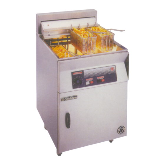
- Page 1 ELECTRIC FRYERS PROUDLY AUSTRALIAN MADE INSTALLATION PROCEDURE – USER MANUAL SERVICE INSTRUCTION MODELS FRE-18D, FRE-24D, FRET-18D FRE-24D FRE-18D FRET-18D ESTABLISHED 1911 The Cooking Equipment Professionals www.goldsteineswood.com.au...
-
Page 2: Table Of Contents
Page 16 WIRING DIAGRAM FET-18 DIGITAL CONTROL Page 17 10a. WIRING DIAGRAM FRE-18D –24 D Page 18 DRAWINGS - SPARE PARTS - FRE-18D-24D Page 19 & 20 DRAWINGS - SPARE PARTS - FRET-18D Page 21 & 22 WARRANTY Page 23... -
Page 3: Introduction
. INTRODUCTION Congratulations for purchasing your Goldstein commercial cooking appliance. J. Goldstein & Co. is a wholly owned Australian company and has been operating since 1911, building high quality products. The information in this manual will assist your installer and ensure correct location and connection. -
Page 4: Installation
2. INSTALLATION RECEIVING INSPECTION – PRE-INSTALLATION Please follow these instructions carefully • Remove baskets and cartons from unit, check contents. • Lift off base and screw the adjustable legs into the base. • Set units in correct position. • Adjust feet till they are all touching the floor and using spirit level, level from front to rear and left to right. - Page 5 2. INSTALLATION Cont’d Please follow these instructions carefully Set unit in desired position. If rear wall is of combustible material ensure there is a minimum distance of 100mm between the back of the unit and the wall. Adjust feet till they are all touching the floor and using a spirit level from front to rear and left to right.
-
Page 6: Commissioning
3. COMMISSIONING COMMISSIONING APPLIANCE – DETAILS, TESTING, CHECKING PRESSURE ETC. COMMISSIONING CHECK LIST CHECK FOR DAMAGE AND MISSING PORTS. REMOVE ALL PLASTIC COATING FROM S/STEEL PANELS. MAKE SURE ALL PARTS ARE IN THEIR CORRECT POSITION E.G. TRAYS ELEMENTS. MAKE SURE ALL ELECTRIC CONNECTIONS ARE CORRECT AND TIGHT. LEVEL OFF UNIT LEFT TO RIGHT AND ALSO MAKE SURE THAT FRONT IS JUST 3-4 MM LOWER TO ALLOW FOR FLUING. -
Page 7: Operating Instructions
4. OPERATING INSTRUCTIONS OPERATING BEFORE FIRST USE Clean protective oil from bright parts and interior of pan with a solution of washing soda or other grease dissolving material. Drain through valve in bottom then rinse thoroughly. (Note: It must be completely rinsed out for even a small particle of cleaner in the pan will ruin the cooking medium). - Page 8 4. OPERATING INSTRUCTIONS Cont’d WEEKLY Completely drain the fryer vessel into either the filter or steel container. Do not use a plastic bucket or glass container. Clean the vessel with a good grade of cleaner or hot water and a strong detergent.
-
Page 9: Draining & Filtering Instructions
5. DRAINING & FILTERING INSTRUCTION A. DRAINING WARNING Draining and filtering of shortening must be accomplished with care to avoid the possibility of a serious burn caused from careless handling. WARNING The element MUST NOT be turned on when the fry pot is empty. A few minutes of element operation with an empty fry pot will destroy the element and void the warranty. - Page 10 DRAINING & FILTERING INSTRUCTIONS Cont’d B. BOILING OUT THE FRYPOTS Clean new fry pots as follows before filling with shortening: Before operating the element, close fryer drain valve and fill empty fry pot with a mixture of cold water and boil-out washing soda solution. Fill to the fry pot OIL-LEVEL LINE at rear of tank.
-
Page 11: Technical Data
TECHNICAL DATA FRE-18D-24D FRET-18D DIGITAL CONTROL SRT 701 CAHO IM013B2/p11... - Page 12 6. TECHNICAL DATA Cont’d SRT-701 CAHO FEATURES Terminal Design: adopts a special design with strong stress, provide good connection. Its also suitably for vibrating PCBs: whole series use double sided PCBs, quality can be assured. PCB’s location: be fixed by vertical type which will not be affected by environment.
-
Page 13: Resistance Vs Temperature
7. RESISTANCE Vs TEMPERATURE RTD Sensors - Table for Platinum resistance elements. R(0) = 100 ohm. Alpha-0.00385. Resistance values in Ohms from 0°C to + 150°C. PT100 ohm RTD to DIN 43760 - IEC 751 °C 100.00 100.39 100.78 101.17 101.54 101.95 102.34... -
Page 14: Servicing
This equipment will need less service if given normal care and frequent cleaning. Have the Electric Commission, appropriate Energy Commission or your service man, check your equipment regularly. GOLDSTEIN fryers are engineered for serviceability. Any part can be quickly and easily removed. - Page 15 For this address and phone number, call the factory. Factory address and phone numbers are on the back of this manual. IMPORTANT GOLDSTEIN & CO WHOSE POLICY IS ONE OF CONSTANT IMPROVEMENT, RESERVES THE RIGHT TO AMEND SPECIFICATIONS OF ANY PART OR ASSEMBLY AND THE MATERIALS AND FINISHES COMPRISING THE COOL ZONE FRYER AND ITS ACCESSORY EQUIPMENT WITHOUT PRIOR NOTICE.
-
Page 16: Trouble Shooting
9. TROUBLE SHOOTING TROUBLE SHOOTING. These troubleshooting procedures must be carried out only by a Goldstein Authorised Maintenance & Repair Centre or Company specialising in restaurant Cooking appliances. The problems and possible solutions given below cover those most commonly encountered. -
Page 17: Wiring Diagram Fet-18 Digital Control
10. WIRING DIAGRAM – FET18 DIGITAL CONTROL FET18 DIGITAL CONTROL ELEMENT 7.0kW ELEMENT 7.0kW CONTACTOR CONTACTOR PROBE PROBE CONTACTOR CONTACTOR OVER TEMP. OVER TEMP. MAIN SWITCH MAIN SWITCH C NO MICRO SWITCH TOLERANCES ON DIMENSIONS UNLESS OTHERWISE SPECIFIED WHOLE mm:±0.5 DECIMALS:±0.2 DATE CHECKED... - Page 18 10a. WIRING DIAGRAM – FRE-18D – 24D IM013B2/p18...
- Page 19 11. DRAWINGS FRE-18D & 24D MODEL: FRE-18/D, FRE-24/D M013B2/p19...
- Page 20 11. SPARE PARTS FRE-18D & 24D ITEM No. CODE DESCRIPTION MBKFE180 BASKET – FRE18 FRE18M02 SCRAP ARRESTER – 355 x 355 FRE24M02 SCRAP ARRESTER – FRE24 FRG18P27 BASKET HOLDER FRG24P27 BASKET HOLDER MTH00238 CONTROL – ELEC. OVERTEMP. (238°C) ESWM0006 MICRO SWITCH EEVM7501 ELEMENT –...
- Page 21 12. DRAWING MODEL: FRET-18D IM013B2/p21...
- Page 22 12. SPARE PARTS MODEL: FRET-18D ITEM No. CODE DESCRIPTION MBKFE180 BASKET – FRE18 FET18M01 SCRAP ARRESTER FRG18P27 BASKET HOLDER MTH00238 CONTROL – ELE OVERTEMP. (238°C) ESWM0006 MICRO SWITCH EEVM7501 ELEMENT – 7KW FRE18 / FRE24 ETC00893 CONTROL – DIGITAL 893 FRYER FRE-D ESW00007 SWITCH –...
-
Page 23: Warranty
GOLDSTEIN/ESWOOD warrants their products to be free from defects in material and workmanship under “normal use and service”. This does not include normal wear and tear of parts. GOLDSTEIN/ESWOOD will repair or replace any parts, which GOLDSTEIN/ESWOOD’s sole... - Page 24 14. J GOLDSTEIN & CO PTY LTD BRANCHES For inquiries please call your nearest state branch: Head Office 211-213 Woodpark Road New South Wales 2564 Phone: 02 9604 7333 Fax: 02 9604 5420 Victoria Queensland Unit 13 Unit 3 260-264 Wickham Road...
Need help?
Do you have a question about the FRE-18D and is the answer not in the manual?
Questions and answers