Table of Contents
Advertisement
Quick Links
- 1 Section 1: Our Recommendations
- 2 Section 4: Kit Contents
- 3 Section 5: Wing Assembly
- 4 Section 10: Landing Gear Installation
- 5 Section 11: Engine Installation
- 6 Section 14: Elevator and Rudder Control Systems Installation
- 7 Section 15: Aileron Control System Installation
- 8 Section 17: Balancing the Big Bee Arf
- Download this manual
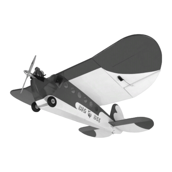
Clancy Aviation has brought the world of the Classic Lazy Bee to new dimensions with this 60" wing span, .40 size engine Big Bee
ARF. Get to the field quickly with this low parts-count, easy-to-assemble aircraft. Flying the Lazy Bee is fun-defined and the Big
Bee ARF brings a new dimension to that style. The poly-tips capture the unique styling and handling of the Lazy Bee but with an
added flair of ailerons for smoother control response. Use them together and you'll find this Bee will perform mild-to-wild
gyrations you only thought possible with fun-fly aircraft. Unique too to the Big Bee ARF is its park flyer-like wing loading. At only
10.5 ounces per square foot and 1150 square inches, it's amazing what the Big Bee ARF can do.
The Lazy Bee flying experience is a unique one, and with the larger Big Bee ARF, you'll find new fun in this special Andy
Clancy design.
INSTRUCTIONS FOR ASSEMBLY
The Clancy Aviation Big Bee ARF is distributed
exclusively by Global Hobby Distributors
18480 Bandilier Circle, Fountain Valley, CA 92708
All contents copyright © 2005, Global Hobby Distributors
Version 2.0 June 2005
BIG BEE ARF SPECIFICATIONS:
Wing Span: 60 Inches (1524mm)
Wing Area: 1150 Square Inches (74dm
Length: 48.75 Inches (1238mm)
Weight RTF: 5.25 - 6 Pounds (148 - 178gr)
Wing Loading: 10.5 - 12 Ounces/Square Foot (2 - 2.3gr/dm
Functions: Ailerons, Elevator, Rudder and Throttle
Engine Required: .32 - .46 Two-Stroke or .40 - .61 Four-Stroke
Radio Required: 4 Channel or More w/5 Standard Servos
Recommended Electric Power Systems:
Astro Flight Cobalt 25 Geared, AXI 2826/10 or Similar with Matching ESC
12-16 Cell NiMH Sub-C or 3-4 Cell 2100-3200mAH LiPO
1
2
)
2
)
Kit Product Number 222212
Advertisement
Table of Contents

Related Manuals for Clancy Aviation Big Bee


Summary of Contents for Clancy Aviation Big Bee
- Page 1 Clancy Aviation has brought the world of the Classic Lazy Bee to new dimensions with this 60" wing span, .40 size engine Big Bee ARF. Get to the field quickly with this low parts-count, easy-to-assemble aircraft. Flying the Lazy Bee is fun-defined and the Big Bee ARF brings a new dimension to that style.
-
Page 2: Table Of Contents
In that Clancy Aviation has no control over the final assembly or material used for final assembly, no liability shall be assumed for any damage resulting from the use by the user of the final user-assembled product. By the act of using the final user-assembled product, the user accepts all... -
Page 3: Introduction
We urge you to come check out our website at http://globalservices.globalhobby.com. There you will find public message boards frequented by other Clancy Aviation product owners and the Global Services support staff. This is a great place to learn about new products, get help and suggestions for your product or just simply hang out and chat with people that share your same interests. -
Page 4: Section 1: Our Recommendations
What Engine Should I Use? The Big Bee ARF is designed to use a .32 - .46 size two-stroke engine or a .40 - .61 size four-stroke engine. The airplane flies great using engines within the recommended size ranges, although for the most speed and best aerobatic performance we suggest using an engine at the upper end of the size range. -
Page 5: Section 2: Tools And Supplies Required
SECTION 3: A NOTE ABOUT COVERING The covering material used on the Clancy Aviation Big Bee ARF is real iron-on, heat-shrink covering material. It is possible with heat and humidity changes that the covering on your airplane may wrinkle or sag. This trait is inherent in all types of heat-shrink material. -
Page 6: Section 4: Kit Contents
SECTION 4: KIT CONTENTS We have organized the parts as they come out of the box for easier identification during assembly. Before you begin assembly, group the parts as we list them below. This will ensure that you have all of the parts before you begin assembly and it will also help you become familiar with each part. -
Page 7: Section 5: Wing Assembly
SECTION 5: WING ASSEMBLY YOU'LL NEED THE FOLLOWING PARTS FROM THE KIT: (1) Wing Center-Section Panel (1) Plywood Wing Mounting Bracket (1) Right Wing Tip Panel w/Aileron (2) Aluminum Wing Joiners (1) Left Wing Tip Panel w/Aileron YOU'LL NEED THE FOLLOWING TOOLS AND SUPPLIES: Kwik Bond 30 Minute Epoxy Masking Tape Excel Modeling Knife... - Page 8 Carefully slide the wing tip panel and the wing center-section panel together with the wing joiner temporarily installed (without using glue). IMPORTANT While sliding the two wing panels together, carefully guide the aileron servo lead pull-string from the hole in the wing center-section panel into the matching hole in the wing tip panel.
- Page 9 Mix a generous amount of 30 minute epoxy and apply a thin layer to the exposed half of the wing joiner, the inside of the wing joiner box in the wing center-section panel, and to the entire gluing surface of BOTH root ribs. Make sure to use enough epoxy to fill any gaps.
-
Page 10: Section 6: Aileron Hinging
Paper Towels NHP Epoxy Mixing Cups Important Information About the Aileron Hinges Included with Your Big Bee ARF The hinges are not glued into place from the factory. You must glue them into place. The ailerons are hinged using plastic steel- pinned hinges that are designed to be glued into place with epoxy. -
Page 11: Section 7: Wing Mounting
When satisfied with the fit and alignment, remove the hinges and carefully apply a thin coat of lightweight oil or petroleum jelly to only the pivot point of each of the three hinges. This will prevent the hinges from being glued solid when you install them. Mix a small quantity of 5 minute epoxy and carefully glue each of the three hinges into only the aileron for now. -
Page 12: Section 8: Stabilizer Installation
IMPORTANT Before gluing the wing-screw doubler into place in the next procedure, make sure to cut away and remove the covering material from the wing where the wing-screw doubler will be glued into place. This will ensure a strong glue joint. Glue the wing-screw doubler to the top of the wing, using a thin layer of 5 minute epoxy. - Page 13 STEP 1: ALIGNING THE HORIZONTAL STABILIZER Using a modeling knife, cut away and remove the covering material from over the stabilizer mounting slot in each side of the fuselage. The slot is located 3" below the top of the fuselage and is 4" long and 3/16"...
- Page 14 When you're satisfied that the stabilizer is square to the wing, use a pencil to draw a mark on each side of the front of the stabilizer where it and the fuselage sides meet, then use a T-Pin to hold the stabilizer firmly in place and aligned.
- Page 15 STEP 3: HINGING THE ELEVATOR Important Information About the C/A-Style Hinges Included with Your Big Bee ARF The hinges are not glued into place from the factory. You must glue them into place. The elevator and rudder are hinged using C/A-style hinges. These hinges are designed to be glued into place using thin C/A. Do not glue these hinges into place using any other type of glue, such as thick C/A or epoxy.
-
Page 16: Section 9: Rudder Installation
SECTION 9: RUDDER INSTALLATION YOU'LL NEED THE FOLLOWING PARTS FROM THE KIT: (1) Rudder (1) Tail Wheel (1) C/A-Style Hinge (Large) (1) Nylon Spacer (1) C/A-Style Hinge (Small) (1) Wheel Collar (1) Prebent Tail Wheel Wire w/Nylon Bearing (1) M3 x 5mm Machine Screw YOU'LL NEED THE FOLLOWING TOOLS AND SUPPLIES: Kwik Bond Thin C/A Ernst Airplane Stand... -
Page 17: Section 10: Landing Gear Installation
Slide the large hinge into the upper hinge slot in the rudder and the small hinge into the lower hinge slot in the rudder, making sure that you push each hinge in up to the T-pins. Don't glue the hinges into place yet. - Page 18 IMPORTANT The wheels included with the Big Bee ARF are suitable for use on hard surfaces, such as concrete, asphalt and hard-packed dirt. If you will be flying off of grass, we suggest replacing the stock wheels with larger wheels. The larger diameter wheels will make it easier to land and take off on grass runways.
-
Page 19: Section 11: Engine Installation
Slide one main gear wheel onto each end of the axle. Secure the wheels into place, using two wheel collars and two M3 x 5mm machine screws. We suggest applying Blue Threadlocker to the machine screws to prevent them from loosening during flight. IMPORTANT After installing the wheel collars, double-check that both wheels spin freely. - Page 20 Temporarily glue the two engine mounting beams to your engine's mounting lugs, using a couple of drops of thick C/A. The location of the engine is not important at this time. It's more important that the beams are square to the mounting lugs. IMPORTANT Note that the lower mounting bracket on the engine mounting beams has been cut shorter to fit the confined space of the firewall.
- Page 21 Using a drill with a 5/32" diameter drill bit, drill a hole through the firewall at each of the four marks you drew. Remove your engine from the mounting beams and install them to the firewall, using four M3 x 20mm socket-cap screws, four M3 flat washers and four M3 blind nuts.
-
Page 22: Section 12: Fuel Tank Assembly And Installation
SECTION 12: FUEL TANK ASSEMBLY AND INSTALLATION YOU'LL NEED THE FOLLOWING PARTS FROM THE KIT: (1) 240cc Fuel Tank (1) Fuel Pick-Up "Clunk" (1) Large Diameter Metal Plate (1) M3 x 20mm Machine Screw (1) Small Diameter Metal Plate (1) Silicone Fuel Tubing (1) Metal Neck-Reinforcement Ring (3) Aluminum Tubing (1) Rubber Stopper... -
Page 23: Section 13: Throttle Control System Installation
STEP 2: INSTALLING THE RUBBER STOPPER ASSEMBLY Carefully push the metal neck-reinforcement ring over the neck of the molded fuel tank opening. Carefully push the rubber stopper assembly into the fuel tank opening and rotate the stopper assembly until the aluminum vent tube rests just below the top of the tank. - Page 24 IMPORTANT INFORMATION ABOUT THROTTLE PUSHROD SETUP FOR FOUR-STROKE ENGINES The hole in the firewall for the throttle pushrod wire has been predrilled from the factory. This hole is positioned to line up with the throttle arm on most two-stroke engines within the specified size range. If you are using a four-stroke engine, the hole will not line up with your engine's throttle arm.
-
Page 25: Section 14: Elevator And Rudder Control Systems Installation
Install the adjustable pushrod connector into the enlarged hole. IMPORTANT When threading on the connector nut, don't tighten the nut completely. You don't want the adjustable connector loose, but you do want the adjustable connector to be able to rotate without binding. - Page 26 STEP 1: INSTALLING YOUR ELEVATOR AND RUDDER SERVOS Install the rubber grommets and brass collets onto your elevator and rudder servos, making sure to install the collets with the flanges toward the bottom of the servos. Install the elevator and rudder servos into the two remaining cutouts in the plywood servo tray, making sure to first drill 1/16"...
- Page 27 STEP 3: INSTALLING THE ELEVATOR CONTROL HORN AND CLEVIS Position one nylon control horn onto the bottom left side of the elevator. When aligned properly, the centerline of the control horn should be about 5/16" out from the side of the fuselage (at the hinge line) and the clevis attachment holes should be lined up over the hinge line.
-
Page 28: Section 15: Aileron Control System Installation
STEP 5: INSTALLING THE RUDDER CONTROL HORN AND CLEVIS Position one nylon control horn onto the right side of the rudder. When aligned properly, the centerline of the control horn should be even with the rudder pushrod wire (at the hinge line) and the clevis attachment holes should be lined up over the hinge line. - Page 29 Plug one 12" servo extension onto each of the aileron servo leads. To prevent the servo leads from pulling apart during assembly, or worse, during flight, secure the plugs together, using a short piece of 3/8" diameter heat-shrink tubing. Using a modeling knife, cut away and remove the covering material from over the two precut aileron servo lead exit holes in the bottom of the wing.
-
Page 30: Section 16: Final Assembly
Position one nylon control horn onto the bottom of one aileron. When aligned properly, the centerline of the control horn should be 2-1/4" out from the inside edge of the aileron (at the hinge line) and the clevis attachment holes should be lined up over the hinge line. The base of the control horn should be parallel to the hinge line, too. - Page 31 STEP 1: INSTALLING THE FUSELAGE HATCH COVER Set the servo hatch cover into place and align it with the bottom of the fuselage. Using a drill with a 1/16" diameter drill bit, drill two pilot holes through the hatch cover for the mounting screws. Position each hole 1/2" in from the fuselage sides and 3/16"...
- Page 32 Using a modeling knife, cut away and remove the covering material from over the six precut window mounting holes below the wing saddle, in each side of the fuselage. PRO TIP Before gluing the windows into place in the next procedure, you may want to paint the exposed edges of the window cutouts, using black paint.
-
Page 33: Section 17: Balancing The Big Bee Arf
6" (152mm). IMPORTANT Balance the Big Bee ARF with the fuel tank empty and the airplane fully assembled. Install the wing onto the fuselage, then apply two short pieces of masking tape onto the bottom of the wing, 5-1/2" (140mm) back from the leading edge, measured at the fuselage sides. -
Page 34: Section 19: Control Throws
SECTION 20: REPLACEMENT PARTS We stock a complete line of replacement parts for your Clancy Aviation Big Bee ARF. Listed below are the replacement parts that are available along with their respective part numbers for easy ordering convenience. We suggest ordering directly from your local dealer. -
Page 35: Product Evaluation Sheet
Global Hobby Distributors will not disclose the information it collects to outside parties. Global Hobby Distributors does not sell, trade, or rent your personal information to others. Your privacy is important to us. Kit: Clancy Aviation Big Bee ARF # 222212 Was any of the assembly difficult for you? If yes, please explain. - Page 36 _____________________________ _____________________________ Post Office will not deliver _____________________________ without proper postage ..........Global Hobby Distributors Attn: Global Services 18480 Bandilier Circle Fountain Valley CA 92728-8610 Fold along dotted line...
Need help?
Do you have a question about the Big Bee and is the answer not in the manual?
Questions and answers