Table of Contents
Advertisement
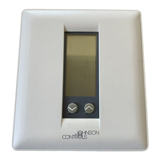
T500 Series Non-Programmable Thermostats
T500 Series Thermostats provide an economical
control solution for single-stage, multi-stage, or heat
pump systems. Two temperature settings can be
selected, as well as heat, cool, automatic
changeover, and off modes.
Thermostats are available in the following types:
T500HCN-1 (1 heat/1 cool), T500HPN-1 (heat pump,
3 heat, 2 cool), T500MSN-1 (2 heat/2 cool). Each
thermostat is packaged with the necessary mounting
hardware, and installation is simple and fast for
reduced cost.
! ! ! ! Low-Profile Design
! ! ! ! No Batteries Required
! ! ! ! Lockable Access Cover and
Keypad Lockout
! ! ! ! Full Function Liquid Crystal
Display (LCD)
©
1999 Johnson Controls, Inc.
Part No. 24-8341-19, Rev. C
Code No. LIT-216178
Figure 1: T500 Series Non-Programmable
Features and Benefits
Compliments any decor
Retains programmed setpoints upon loss of
power
Prevents unauthorized changes
Makes controls easy to read, easy to use
Optimizes control performance
Fans 216, 1628.3
Product/Technical Bulletin
Issue Date
Thermostats
www.johnsoncontrols.com
T500
0899
1
Advertisement
Table of Contents

Subscribe to Our Youtube Channel
Related Manuals for Johnson T500 Series


Summary of Contents for Johnson T500 Series
- Page 1 Product/Technical Bulletin T500 Issue Date 0899 T500 Series Non-Programmable Thermostats T500 Series Thermostats provide an economical control solution for single-stage, multi-stage, or heat pump systems. Two temperature settings can be selected, as well as heat, cool, automatic changeover, and off modes.
- Page 2 Table 4, Table 5, or Table 6. Push extra wire back into the wall. Wires must be flush to the plastic base. Plug hole with a fireproof material to prevent drafts from affecting the ambient temperature readings. T500 Series Non-Programmable Thermostats Product/Technical Bulletin...
- Page 3 Short-circuited or improperly connected wires may result in permanent damage to the unit. Mount Figure 4: Mounting the Base Figure 3: Separating the T500 from the Base T500 Series Non-Programmable Thermostats Product/Technical Bulletin...
- Page 4 Use caution to avoid cracking the thermostat base or cover. Hinged Tabs Plastic Lock Pin Thermostat Base Figure 6: Installing the T500 Thermostat Snap plastic lock into place. Figure 5: Installing the Thermostat Lock T500 Series Non-Programmable Thermostats Product/Technical Bulletin...
- Page 5 However, in cooling mode, allows the fan to operate immediately with a call for cooling. In heating or cooling mode, allows the fan to operate immediately with a call for heat or cooling. T500 Series Non-Programmable Thermostats Product/Technical Bulletin...
- Page 6 Allows single-stage heating or cooling. LED 1 icon Optional selection: LCD icon comes on with LED 1. off/on (See Table 7.) LED 2 icon Optional selection: LCD icon comes on with LED 2. off/on (See Table 7.) T500 Series Non-Programmable Thermostats Product/Technical Bulletin...
- Page 7 Allows single-stage heating or cooling. LED 1 icon off/on Optional selection: LCD icon comes on with LED 1. (See Table 7.) LED 2 icon off/on Optional selection: LCD icon comes on with LED 2. (See Table 7.) T500 Series Non-Programmable Thermostats Product/Technical Bulletin...
- Page 8 Connections for remote clock/timer for alternate setpoints CLK2 Connections for outdoor air temperature or indoor remote sensors; refer to instructions included with sensors RS+V CLK1 Heating CLK2 Cooling RS+V 24VAC Common 24V(c) Hcn-1wire Figure 8: T500HCN-1 Wiring Configuration T500 Series Non-Programmable Thermostats Product/Technical Bulletin...
- Page 9 1st Stage Cooling sensors CLK2 Energizes reversing valve in the 24VAC cooling mode Common RS+V Cool Reversing Valve Energizes reversing valve in the Heat Reversing Valve heating mode Hpn-1wire Figure 10: T500HPN-1 Wiring Configuration T500 Series Non-Programmable Thermostats Product/Technical Bulletin...
- Page 10 CLK2 1st Stage Cooling CLK1 CLK2 Connection for outdoor temperature sensor and/or indoor remote sensor 24VAC option; refer to instructions included RS+V Common RS+V with sensors MSN-1Wire Figure 12: T500MSN-1 Wiring Configuration T500 Series Non-Programmable Thermostats Product/Technical Bulletin...
- Page 11 J 1 to disconnect R and 24V(c). Electronics Thermostat CLK1 CLK2 24V(c) RS+V RS1 Equipment 1st Stage Heat Remote Remote 1st Stage Clock/Timer Sensor Compressor (if used) (if used) Hcn-1 Optional Figure 13: T500HCN-1 Wiring Schematic T500 Series Non-Programmable Thermostats Product/Technical Bulletin...
- Page 12 LED2 CLK2 Equipment LED1 CLK1 1st Stage 2nd Stage Heat Heat Remote Remote 1st Stage 2nd Stage Clock/Timer Sensor Cool Cool (if used) (if used) Optional Field Contact Switches Figure 15: T500MSN-1 Wiring Schematic T500 Series Non-Programmable Thermostats Product/Technical Bulletin...
- Page 13 (optional). Day/Night Used to alternate between day Used to run fan and night setpoints. continuously. Used to increase/decrease values or change between Degree C or F. Face Figure 16: T500 Non-Programmable Pushbuttons T500 Series Non-Programmable Thermostats Product/Technical Bulletin...
-
Page 14: Outdoor Button
If continuous fan is not selected, the fan will operate automatically and the fan symbol will be off. To select continuous fan operation, press the Fan button. The Fan symbol will be displayed. (See Figure 17.) T500 Series Non-Programmable Thermostats Product/Technical Bulletin... -
Page 15: Outdoor Sensor
2. Adjust the temperature with the ∨ ∨ ∨ ∨ or ∧ ∧ ∧ ∧ buttons. The temperature is shown on the lower display to the hundredths place. For example, 72°F on the large display is shown as 72 13. T500 Series Non-Programmable Thermostats Product/Technical Bulletin... - Page 16 2. Press the ∨ ∨ ∨ ∨ or ∧ ∧ ∧ ∧ buttons to raise the setpoint Npiface3 above or below the current ambient temperature. The thermostat should call for either heating or Figure 18: Verifying Proper Operation cooling, and should activate the fan. T500 Series Non-Programmable Thermostats Product/Technical Bulletin...
- Page 17 * The Non-Programmable T500 Thermostats do not have a supercap back up. The “AC” on the LCD will therefore never flash. LCD shows missing or LCD failure Replace the unit. extra segments ... T500 Series Non-Programmable Thermostats Product/Technical Bulletin...
- Page 18 Replacement Duct Mount Temperature Sensor (includes mounting hardware) SEN-500-605 Table 12: Repair Parts Item Product Code Number 3 in. Sensor Probe (use with outdoor air sensor) SEN-500-601 8 in. Sensor Probe (use with duct mount sensor) SEN-500-602 T500 Series Non-Programmable Thermostats Product/Technical Bulletin...
- Page 19 Notes T500 Series Non-Programmable Thermostats Product/Technical Bulletin...
- Page 20 The performance specifications are nominal and conform to acceptable industry standards. For application at conditions beyond these specifications, consult the local Johnson Controls office. Johnson Controls, Inc. shall not be liable for damages resulting from misapplication or misuse of its products This device complies with Class A Part 15 of the FCC rules.
Need help?
Do you have a question about the T500 Series and is the answer not in the manual?
Questions and answers