Table of Contents
Advertisement
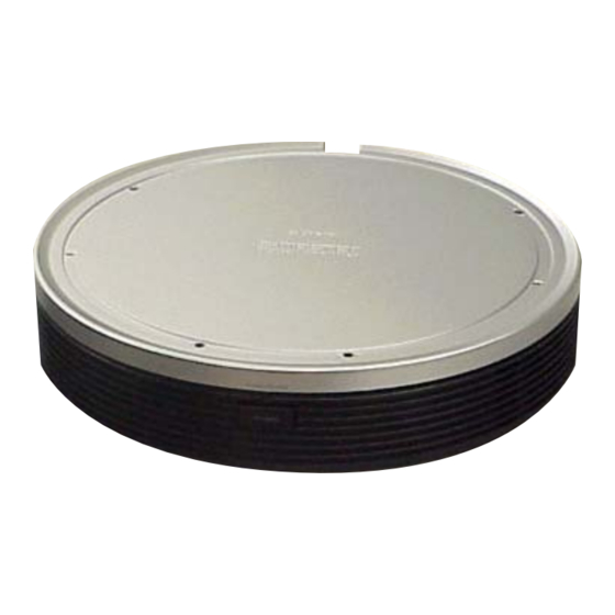
SERVICE MANUAL
Ver. 1.2 2006.09
TA-WR4 is the surround amplifier section
in DAV-DZ810W/DZ820KW/FX900W/
FX900KW.
Sony Corporation
9-887-226-03
Home Audio Division
2006I16-1
Published by Sony Techno Create Corporation
© 2006.09
SPECIFICATIONS
POWER OUTPUT AND
TOTAL HARMONIC
D
ISTORTION
(FTC Output Power)
:
US and Canadian models
SL/SR: 84 W/ch 3 ohms at
160 - 20,000 Hz,
0.7 % THD
Surround mode (reference) RMS output power, 10 %
THD
Latin American models:
130 W + 130 W
(with SS-TS55,
SS-TS56W)
Argentine and other models:
140 W + 140 W
(with SS-TS55,
SS-TS56W)
Power requirements
Latin American models:
110 - 240 V AC, 50/60 Hz
:
120 V AC, 60 Hz
US and Canadian models
Other models:
220 - 240 V AC, 50/60 Hz
120 V AC, 50/60 Hz
Taiwan model :
Power consumption
50 W
Dimensions (approx.)
280 60 280 mm (w/h/d)
Mass (approx.)
1.6 kg
Design and specifications are subject to change
without notice.
TA-WR4
US Model
Canadian Model
AEP Model
UK Model
Australian Model
SURROUND AMPLIFIER
E Model
Advertisement
Table of Contents

Related Manuals for Sony TA-WR4


Summary of Contents for Sony TA-WR4
-
Page 1: Service Manual
SERVICE MANUAL US Model Canadian Model Ver. 1.2 2006.09 AEP Model UK Model E Model Australian Model TA-WR4 is the surround amplifier section in DAV-DZ810W/DZ820KW/FX900W/ FX900KW. SPECIFICATIONS POWER OUTPUT AND TOTAL HARMONIC ISTORTION (FTC Output Power) US and Canadian models... -
Page 2: Table Of Contents
DIAGRAMMES SCHÉMATIQUES ET LA LISTE DES PIÈCES SONT Parts on Set CRITIQUES POUR LA SÉCURITÉ DE FONCTIONNEMENT. NE REMPLACER CES COMPOSANTS QUE PAR DES PIÈSES SONY DONT LES NUMÉROS SONT DONNÉS DANS CE MANUEL OU DANS LES SUPPÉMENTS PUBLIÉS PAR SONY. -
Page 3: General
TA-WR4 SECTION 1 GENERAL This section is extracted from instruction manual. Surround amplifier Front panel POWER / ON LINE POWER Rear panel SPEAKER SS-TS56W SUR L SUR R A POWER/ON LINE indicator (23) C SS-TS56W jack (16) B POWER (23) -
Page 4: Diagrams
TA-WR4 Ver. 1.2 SECTION 2 DIAGRAMS • Note for Printed Wiring Boards and Schematic Diagrams Note on Printed Wiring Boards: Note on Schematic Diagrams: • All capacitors are in µF unless otherwise noted. (p: pF) • X : parts extracted from the component side. -
Page 5: Block Diagram
TA-WR4 Ver. 1.2 2-1. BLOCK DIAGRAM IC102 IC109 IC301 IC100 RF DEMODULATOR T100 AND GATE STREAM PROCESSOR POWER AMP A/D CONVERTER SPEAKER L304 J310 DATA DAOUT/ 10 ADVIN DATA OUTL1 6 PWM_A OUT A SS-TS56W ROUT SUR R OUT A... -
Page 6: Printed Wiring Board - Rx Amp Board
TA-WR4 Ver. 1.1 2-2. PRINTED WIRING BOARD — RX AMP BOARD — :Uses unleaded solder. (SIDE A) • Semiconductor Location C336 C317 Ref. No. Location R330 R324 D100 C327 L304 C340 D101 C339 R322 IC104 D102 C322 D201 R333 R319... -
Page 7: Schematic Diagram - Rx Amp Board (1/4)
TA-WR4 2-3. SCHEMATIC DIAGRAM — RX AMP BOARD (1/4) — • See page 4 for Waveform. • See page 13 for IC Block Diagrams. RX AMP BOARD (1/4) C346 C345 10 50V R330 IC104 TK11225CMCL-G FB103 L307 0UH 0.2A C344... -
Page 8: Schematic Diagram - Rx Amp Board (2/4)
TA-WR4 2-4. SCHEMATIC DIAGRAM — RX AMP BOARD (2/4) — • See page 4 for Waveform. • See page 13 for IC Block Diagram. • See page 17 for IC Pin Function Description. CN303 RX AMP BOARD (2/4) D100 SPR-54MVW... -
Page 9: Schematic Diagram - Rx Amp Board (3/4)
TA-WR4 Ver. 1.1 2-5. SCHEMATIC DIAGRAM — RX AMP BOARD (3/4) — • See page 4 for Waveform. • See page 14 for IC Block Diagrams. RX AMP BOARD (3/4) R101 R102 R201 R202 L3055 C401 47 16V C418 L3054... -
Page 10: Schematic Diagram - Rx Amp Board (4/4)
TA-WR4 Ver. 1.1 2-6. SCHEMATIC DIAGRAM — RX AMP BOARD (4/4) — • See page 16 for IC Pin Function Description. T100 TERMINAL BOARD RX AMP BOARD (4/4) L111 L112 R267 1.2k : EXCEPT E32 L212 2.2k : E32 L211... -
Page 11: Printed Wiring Boards - Power Section
TA-WR4 Ver. 1.2 2-7. PRINTED WIRING BOARD — POWER SECTION — :Uses unleaded solder. • Semiconductor Location Ref. No. Location D901 D902 D904 D905 S901 D906 POWER D907 D908 D909 D910 D911 D913 D914 CN901 D916 D917 CN902 D918 D921... -
Page 12: Schematic Diagram - Power Section
TA-WR4 Ver. 1.2 2-8. SCHEMATIC DIAGRAM — POWER SECTION — • See page 15 for IC Block Diagram. CN902 CN901 S901 US, CND, TW EXCEPT US, CND, TW PC902 R917 R922 TLP421F(D4-GR) 5A/125V : US, CND, TW C915 T3.15AL/250V : EXCEPT US, CND, E32, TW... -
Page 13: Ic Block Diagrams
TA-WR4 • IC Block Diagrams – RX AMP Board – IC101 XC62HR1502MR VOUT CURRENT LIMIT – OUTPUT REFERENCE CONTROL VOLTAGE IC102 CXD4017R 63 62 61 60 59 58 57 56 53 52 51 50 49 MST 1 TEST4 BUFFER XSM 2... - Page 14 TA-WR4 IC110 NJM2374AE (TE2) IC111 SI-3120KM-TL CS 1 – IPK SENSE LOGIC ES 2 CT 3 – – GND 4 VREF COMPARATOR ERROR AMP IC113 TK11118CSCL-G OVER HEAT & OVER CURRENT PROTECTION CONTROL CIRCUIT BANDGAP REFERENCE IC301 CXD9876R CLOCK CLOCK...
- Page 15 TA-WR4 Ver. 1.2 – DIAT POWER Board – IC901 STR-W6735N (US, CND, TW), STR-W6765N (EXCEPT US, CND, TW) DRIVE REGULATOR REGULATOR PROTECTION START/STOP & ICONST – LATCH BURST DELAY BURST CONTROL NC 2 S/GND 3 VCC 4 OLP/SS 5 –...
- Page 16 TA-WR4 • IC Pin Function Description RX AMP BOARD IC100, IC200 CXD9883M Pin No. Pin Name Description BST_A Bootstrap terminal for half bridge A GVDD_A — Gate drive voltage terminal for half bridge A /OTW Overheating wiring detection output terminal...
- Page 17 TA-WR4 RX AMP BOARD IC107 MB89537APFM-G-1018E1 (SYSTEM CONTROLLER) Pin No. Pin Name Description — Not used MOD2 Setting terminal for the CPU operation mode Fixed at “L” in this set 3, 4 — Not used MODEL Setting terminal for the model...
- Page 18 TA-WR4 Pin No. Pin Name Description MAIN_OFF Power off control signal output to the power control “H”: power off V_CONT Voltage control PWM signal output to the shunt regulator DAMP_LATCH Latch control signal output to the stream processor DAMP_SHIFT Shift clock signal output to the stream processor...
-
Page 19: Exploded Views
TA-WR4 Ver. 1.2 SECTION 3 EXPLODED VIEWS NOTE: : Korean model • -XX and -X mean standardized parts, so they • The mechanical parts with no reference : Russian model may have some difference from the original number in the exploded views are not supplied. -
Page 20: Amp Section
TA-WR4 Ver. 1.2 3-2. AMP SECTION M901 supplied supplied F901 supplied supplied supplied supplied Ref. No. Part No. Description Remark Ref. No. Part No. Description Remark 2-677-839-01 +PWH 3X8 (SUMITITE) A-1169-447-A DIAT POWER BOARD, COMPLETE (TW) A-1169-356-A RX AMP BOARD, COMPLETE (EXCEPT E32) 0 F901 1-532-237-00 FUSE TIME-LAG T3.15A/250V... -
Page 21: Electrical Parts List
TA-WR4 Ver. 1.2 SECTION 4 DIAT POWER ELECTRICAL PARTS LIST NOTE: • Due to standardization, replacements in the • -XX and -X mean standardized parts, so they When indicating parts by reference number, parts list may be different from the parts may have some difference from the original please include the board name. - Page 22 TA-WR4 Ver. 1.2 DIAT POWER POWER SWITCH RX AMP Ref. No. Part No. Description Remark Ref. No. Part No. Description Remark FH902 1-533-313-11 FUSE HOLDER 0 R922 1-247-871-91 CARBON 1/4W (EXCEPT US, CND, TW) < RESISTOR > 0 R926 1-216-864-11 SHORT CHIP...
- Page 23 TA-WR4 Ver. 1.1 RX AMP Ref. No. Part No. Description Remark Ref. No. Part No. Description Remark C106 1-104-329-11 CERAMIC CHIP 0.1uF C334 1-162-927-11 CERAMIC CHIP 100PF C107 1-165-739-31 ELECT 56uF C335 1-107-826-11 CERAMIC CHIP 0.1uF C108 1-104-329-11 CERAMIC CHIP 0.1uF...
- Page 24 TA-WR4 Ver. 1.1 RX AMP Ref. No. Part No. Description Remark Ref. No. Part No. Description Remark C403 1-164-156-11 CERAMIC CHIP 0.1uF IC109 8-759-679-55 IC SN74LVC08APWR C404 1-164-156-11 CERAMIC CHIP 0.1uF C405 1-164-156-11 CERAMIC CHIP 0.1uF IC110 6-703-978-01 IC NJM2374AE (TE2)
- Page 25 TA-WR4 Ver. 1.1 RX AMP Ref. No. Part No. Description Remark Ref. No. Part No. Description Remark R108 1-216-864-11 SHORT CHIP R326 1-216-809-11 METAL CHIP 1/10W R109 1-216-864-11 SHORT CHIP R327 1-216-809-11 METAL CHIP 1/10W R110 1-216-864-11 SHORT CHIP R328...
- Page 26 TA-WR4 Ver. 1.2 RX AMP Ref. No. Part No. Description Remark R387 1-216-823-11 METAL CHIP 1.5K 1/10W R388 1-216-821-11 METAL CHIP 1/10W R389 1-218-446-11 METAL CHIP 1/10W R390 1-218-446-11 METAL CHIP 1/10W R395 1-216-864-11 SHORT CHIP R397 1-216-841-11 METAL CHIP...
- Page 27 TA-WR4 MEMO...
-
Page 28: Revision History
TA-WR4 REVISION HISTORY Clicking the version allows you to jump to the revised page. Also, clicking the version at the upper right on the revised page allows you to jump to the next revised page. Ver. Date Description of Revision 2006.04...
Need help?
Do you have a question about the TA-WR4 and is the answer not in the manual?
Questions and answers