Table of Contents
Advertisement
Quick Links
Advertisement
Table of Contents

Related Manuals for Super Systems 31095

Summary of Contents for Super Systems 31095
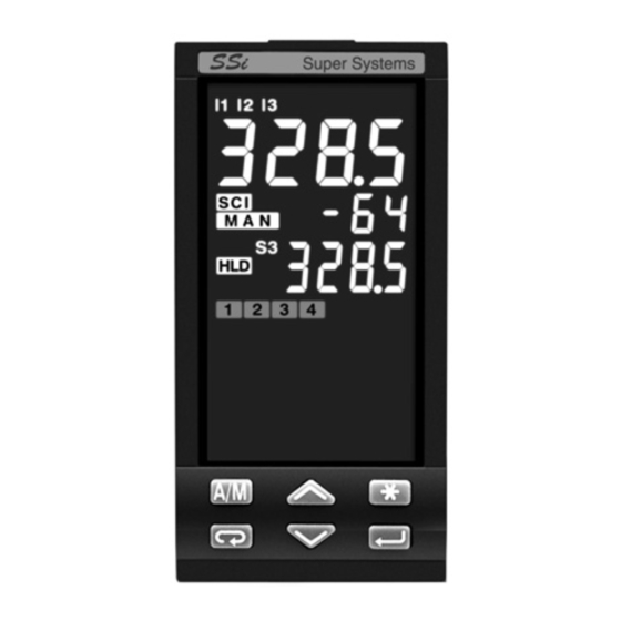
- Page 1 Temperature Controller Model No. 31095 and 31097 Instruction manual I 1 I 2 I 3 45. 8 0 PN 31095 PN 31097 45. 8 0 Super System inc. 7205 Edington Drive Cincinnati, Ohio 45249 United States Phone: 513-772-0060 Toll free: 800-666-4330 Fax: 513-772-9466 www.supersystem.com...
- Page 2 Information Please read these instructions carefully before proceeding with the installation of the controller. Class II instrument (for indoor use only). OTES ON ELECTRIC This controller has been designed in compliance with: Regulations on electrical apparatus (appliance, systems and installations) according to SAFETY AND the European Community directive no.
-
Page 3: Table Of Contents
Table of contents TABLE OF CONTENTS INTRODUCTION DISPLAYS page page ................................................page page RODUCT ODING TANDARD DISPLAY ....................................page FAST ACCESS ......................INSTALLATION page ......................... COMMANDS page page ESCRIPTION ..............................................page page NVIRONMENTAL RATINGS EYPAD OMMANDS ................................ -
Page 4: Introduction
1 - Introduction 1 INTRODUCTION Operating mode Resources The 31095 has been designed Memory Chip for use in industrial Control Alarms Retransmission Data copy/Data store environments. The 31095 is a (option) universal controller with many Main universal input (option) PV/SP/MV standard features. -
Page 5: Product Coding
Triac - Triac Instrument label 45. 8 0 Serial Communications www.supersystem.com None Cincinnati, Ohio USA RS485 Modbus/Jbus SLAVE 5 : 31095 PROFIBUS DP SLAVE : X5-3150-0300 RS485 Modbus/Jbus SLAVE : A0A-0819/1208 + PROFIBUS (L-N) : 100÷240V 50/60 Hz - 5W... -
Page 6: Installation
2 - Installation INSTALLATION 2.1 GENERAL DESCRIPTION IP 20 Terminal Block Installation must be carried out by EN61010 - 1 (IEC1010 - 1) qualified personnel. Panel Before proceeding with the installation of surface this controller, read the instructions in this manual. - Page 7 2 - Installation 2.1.1 DIMENSIONAL DETAILS 2.1.2 PANEL CUT-OUT mm min 1.89 2.56 in min 3.78 mm max. mm max. 0.39 0.39 in max. in max. 4.33 +0.6 mm 1.78 +0.023 in...
-
Page 8: Environmental Ratings
2 - Installation 2.2 ENVIRONMENTAL RATINGS Operating conditions Altitude: up to 2,000 m Temperature: 0…50°C [1] Relative humidity: 5…95 % non-condensing Special conditions Suggestions Altitude: > 2,000 m Use 24Vac supply version Temperature: >50°C Use forced air ventilation Humidity: > 95 % Warm up Use filter Conducting atmosphere... -
Page 9: Panel Mounting
2 - Installation PANEL MOUNTING [1] 2.3.1 INSERT 2.3.2 INSTALLATION 2.3.3 CLAMP 2.3.4 INSTRUMENT THE INSTRUMENT SECURING REMOVAL REMOVAL 1 Prepare panel cut-out; 1 Fit the mounting clamps; 1 Insert the screwdriver in the 1 Push and 2 Check front panel gasket 2 Push the mounting clamps clips of the clamps;... -
Page 10: Electrical Connections
3 - Electrical Connections ELECTRICAL 3.1 TERMINAL BLOCK [1] CONNECTIONS Rear 5.7 mm terminal 0.22 in cover Cable size 1 mm 35 screw terminals M3 Option terminals Holding screw 0.5 Nm (option) Phillips screwdriver PH1 22 N/C Flat blade screwdriver 24V—... - Page 11 3 - Electrical Connections PRECAUTIONS 3.2 SUGGESTED WIRES ROUTING The instrument has been designed to work in an harsh Conduit for supply and output cables and noisy environmental (level IV of the industrial standard IEC 801-4). It is recommended to follow the following suggestions.
-
Page 12: Example Of Wiring Diagram
3 - Electrical Connections 3.3 EXAMPLE OF WIRING DIAGRAM (VALVE CONTROL) Retransm. Commands Supervisory Notes: 1] Ensure that the power supply voltage is Power supply the same as that on the instrument label. switch 2] Switch ON the power supply only after RS485 all electrical connections have been completed. - Page 13 3 - Electrical Connections 3.3.1 POWER SUPPLY 3.3.2 PV CONTROL INPUT Switching power supply with mul- A L-J-K-S-R-T-B-N-E-W thermocouple type Wire resistance tiple isolation and PTC protection. • Connect wires with the polarity as shown; • Standard version: • Always use compensation cable of the correct type 150Ω...
- Page 14 3 - Electrical Connections 3.3.2 PV CONTROL INPUT C For mA, mV C1 With 2 wires transducer Transmitters V,mV mA 24V– 4…20mA Input resistance = 30Ω per mA; Input resistance > 10MΩ per mV; C2 With 3 wires transducer Input resistance = 10kΩ per Volt; Transmitters 24V–...
- Page 15 3 - Electrical Connections 3.3.4 AUXILIARY INPUT 3.3.5 DIGITAL INPUT A - From Remote Setpoint B - From Potentiometer Isolated • The input is active when o.c. o.c. contact Current 0/4…20mA; the logic state is ON, For the measure of the posi- Input resistance = 30Ω.
- Page 16 3 - Electrical Connections 3.3.6 OP1 - OP2 - OP3 - OP4 - OP5 - OP6 OUTPUTS (OPTION) The functionality associated to each of OP1, OP2, OP4, OP5 and OP6 is defined during the configuration of the instrument. The allowed combinations are: Control outputs Alarms Retransmission...
- Page 17 3 - Electrical Connections 3.3.6-A SINGLE ACTION RELAY 3.3.6-C DOUBLE ACTION (TRIAC) CONTROL OUTPUT RELAY (TRIAC)/RELAY (TRIAC) CONTROL OUTPUT Fuse Fuse Coil of the heat Coil of the heat load contactor load contactor Fuse Coil of the cool load contactor 3.3.6-B1 SINGLE ACTION LOGIC 3.3.6-D1 DOUBLE ACTION CONTROL OUTPUT...
- Page 18 3 - Electrical Connections 3.3.6-E1 DOUBLE ACTION Notes for pages 17 - 18 - 19 DIGITAL/RELAY (TRIAC) CONTROL OUTPUT OP1 - OP2 Relay output • SPST Relay N.O., 2A/250 Vac (4A/120Vac) Static for resistive load, Relay • Fuse 2A ac T at 250V, 4A ac T at 110V. OP1 - OP2 Triac output Heat Fuse...
- Page 19 3 - Electrical Connections 3.3.6-F2 DOUBLE ACTION CONTROL OUTPUT 3.3.6-G MOTOR POSITIONER OUTPUT DIGITAL/ANALOG RELAY (TRIAC) / RELAY (TRIAC) Valve drive PID without potentiometer 3 pole Static output with N.O. contacts (raise, lower, stop) Relay V,mV Cool load Raise Heat load Lower 3.3.6-F3 DOUBLE ACTION CONTROL OUTPUT...
- Page 20 3 - Electrical Connections 3.3.7 OP1-2-3-4 ALARM OUTPUTS 3.3.8 OP5 AND OP6 (OPTION) 3.3.9 SERIAL COMMUNICATIONS ANALOG CONTROL OUTPUTS (OPTION) [2] Fuse SLAVE mA mV,V AL3 load Heat load AL3 load Fuse V,mV Fuse • Galvanic isolation 500Vac/1 min; Cool load Compliance to the EIA RS485 standard AL4 load...
- Page 21 3 - Electrical Connections 3.3.10 PROFIBUS DP (OPTION) Termination resistors 220Ω and To make the connections easier, a D-Sub type (9 poles) 390Ω ( W, ±5%) for external connector, model AP-ADP-PRESA-DSUB/9P is provided mounting on the first and end- Must be used with a 9PIN male ERNI type part no. 103648 or sim- ing PROFIBUS stations only.
-
Page 22: Operations
4 - Operation OPERATION 4.1.1 KEY FUNCTIONS AND DISPLAYS IN OPERATOR MODE Digital input status LEDs (yellows) Over range Under range ó - IL1 active 8888 ____ 8888 ---- ò - IL2 active ô - IL3 active I 1 I 2 I 3 45. -
Page 23: P Arameter Setting
4 - Operation 4.1.2 KEY FUNCTIONS AND DISPLAY IN PROGRAMMING MODE The parameter setting proce- dure has a timeout. If no keys Parameter value 35. 0 are pressed for, at least 30 seconds, the controller auto- matically switches back to the operator mode. - Page 24 4 - Operation 4.2 PARAMETER SETTING 4.2.1 NUMERIC ENTRY 4.2.2 MNEMONIC CODE SETTING 274. 8 Operator mode (i.e. the modification of the Setpoint (e.g. configuration see page 26) 275. 0 working Setpoint Press the to display the next or previous mnemonic value from 275.0 to 240.0 ) displayed for the selected parameter.
-
Page 25: Operator Mode
4 - Operation CONFIGURATION PROCEDURE Enter the configuration password 274. 8 Conf Operator Configuration from -999...9999 Mode menu (33 default from factory) 275. 8 Menu C. p as Must be equal to the value of the parameter C. P as (see page.50) Press the key until Back to the operator mode... - Page 26 4 - Operation 4.3.1 INPUTS CONFIGURATION Tab. 1 Input type Tab. 2 Engineering units InP. LINEAR INPUT Value Description Value Description é I nP. PInp. é U nit ONLY 0…600°C 32…1112°F None tc. j none Conf 0…1200°C 32…2192°F Degree centigrade tc.
- Page 27 4 - Operation 4.3.2 SETPOINT CONFIGURATION Tab. 3 Setpoint type S. P . Value Description é S . P . t y Local only Conf Remote only Local/remote only Local - trim loc. t Remote - trim reM. t é L oc é...
- Page 28 4 - Operation 4.3.3 OUTPUT CONFIGURATION é O FF WITH OPTIONAL OP6 ANALOG WITH OP5 ANALOG OUTPUT NOT Secondary output OUTPUT NOT USED AS COOL CON- S. C . O P Conf (Cool) USED AS CONTROL OUTPUT TROL OUTPUT (Heat/Cool only) see table 7 é...
- Page 29 4 - Operation RETRANSMISSION When OP5 and OP6 outputs Retransmission # r t. H 1 Tab. 5 Control mode Tab. 7 Secondary output (Cool) high are not configured as control Value Description é C n. t y Value Description é S .
- Page 30 4 - Operation 4.3.4 DIGITAL INPUT CONFIGURATION 4.3.5 ALARM CONFIGURATION é O FF Tab. 10 Digital Inputs L. i np AL1 alarm type functions é I l1 AL. 1 see table 11 é I l2 Conf Conf Value Description é I l3 Not used NOT AVAILABLE...
- Page 31 4 - Operation é O FF é O FF é O FF Tab. 11 Alarm type AL2 alarm type AL3 alarm type AL4 alarm type é A l 1 AL. 2 AL. 3 AL. 4 see table 11 see table 11 see table 11 é...
- Page 32 4 - Operation [B] ALARM ACKNOWLEDGE 4.3.6 AL1, AL2, AL3, AL4 ALARM CONFIGURATION [A] OPERATING CONDITIONS FUNCTION Absolute alarm Up to four alarms can be config- Alarm occurrence display The alarm, once occurred, is ured: AL1, AL2, AL3 and AL4 (see This function can be enabled by the presented on the display until Active high...
- Page 33 4 - Operation [C] START-UP DISABLING [D] ALARM DISABLING AT SENSOR BREAK LOOP BREAK ALARM (LBA) For those alarms that are configured to be different than LBA, it is possible When the controller connection to # d onb to set the parameter (disable on break).
-
Page 34: Parameters
4 - Operation 4.3.7 TIMER CONFIGURATION PARAMETERIZATION - MAIN MENU tiMe Timer and Start-up 274. 8 Operator t. M od Timer/Start-up Menu cont mode operating mode (see table 1 page 37) 275. 0 The parameter setting procedure has a timeout. If no keys are pressed for, at least, 30 seconds, TIMER FUNCTION START-UP FUNCTION... - Page 35 4 - Operation After having selected the parameter or the code, press $ or % to modify the value (see page 24) The value is entered when the next parameter is selected, by pressing the è key. Pressing í go back to the Operator mode Tuning Input Output...
- Page 36 4 - Operation é L oc S. P . 4.4.1 PARAMETERIZATION - SETPOINT MENU Setpoint menu Depending on the configuration index shown on page 27, Setpoint selection Menu local/remote the following parameters may or may not be present. [1] The units of the slope parameters are Digit/s, digit/min digit/h LOCAL/REMOTE, LOCAL WITH TRIM OR LOCAL ONLY...
-
Page 37: Commands
4 - Operation 4.4.4.2 TIMER FUNCTION Timer/Start-up Timer Timer OP # t . M od # t . A ct # t dop The Timer cannot be operating mode Action function enabled with Heat/Cool This parameter can be defined: This parameter can be defined: std/eHpd control. - Page 38 4 - Operation 4.4.4.2 TIMER FUNCTION TIMER COUNTING MODES A - Counting start time inside the band, B - Counting start time inside the band, C - Counting start time = timer launch end in control mode. end with control output forced to zero. time, end in control mode.
- Page 39 4 - Operation TIMER COUNTING MODES D - Counting start time = timer launch time, E - No control action during F - Control action with stand-by Setpoint end with control output forced to zero. the counting time. during the counting time. The time counting starts when the timer is The time counting starts when the timer is The time counting starts when the timer is...
- Page 40 4 - Operation 4.4.4.2 TIMER FUNCTION (OPTION) POWER FAILURE If there is a power failure dur- TIMER START TIMER REMAINING TIME ing the Timer execution, the When the timer is running it is value of the elapsed time is lost. possible to see the remaining See the Timer starting procedure Depending on Timer action...
- Page 41 4 - Operation 4.4.2 PARAMETERIZATION - ALARMS MENU é é [1] A code, specifying the No. and the Alarms menu alarm type that has been config- Alarm 1 hysteresis Alarm 3 hysteresis hy. I u hy. 3 u ured (see page 31), is displayed. At asymmetric upper asymmetric upper 0…5% Span...
- Page 42 4 - Operation 4.4.3 PARAMETERIZATION - PID MENU (not shown for ON-OFF control action) Menu Menu é é é O FF é Proportional Error Proportional band P. b . d. E rr P. b . C band dead band Cool channel 0.5…999.9%c.s.
- Page 43 4 - Operation 4.4.4 PARAMETERIZATION 4.4.5 PARAMETERIZATION TUNING MENU (not shown for ON-OFF control action) INPUT MENU Tune Tuning Input for AT menu menu Menu Menu Calculated Proportional p. b . band [1] (display only) (available when adap- tive tune is selected) é...
- Page 44 4 - Operation 4.4.6 PARAMETERIZATION - OUTPUT MENU é 10:0 Output Cycle time t. c . (time proportional only) menu 0.2…100.0 s Menu é Control Output low limit Valve drive Heat / Cool OP. L (not available in algorithm Algorithm Heat/Cool configuration) 0…100% é...
- Page 45 4 - Operation CoMM 4.4.7 PARAMETERIZATION - SERIAL COMMUNICATION MENU Serial Menu Depending on serial communication choosen (see model code communication on page 5), there are the following parameters: menu Index RS485 Modbus/Jbus c= 7-8 SLAVE + PROFIBUS DP é Add.
- Page 46 4 - Operation PARAMETERS 4.5.1 SETPOINT MENU Otherwise, the Setpoint value is Setpoint # s . P . L 1st stored For a simpler use of the con- # S . P . 1 obtained according to the con- low limit Setpoint troller, the parameters have been figured rate of change.
- Page 47 4 - Operation Remote Setpoint Bias and Ratio Stored Setpoint # S . P . t r Remote # r tio Setpoint Ratio Tracking Remote signal (see chapter 4.3.2 at page 27) Ratio is the coefficient which Two different operation mode defines the remote Setpoint bias = 20 can be set:...
- Page 48 4 - Operation 4.5.1 SETPOINT MENU 4.5.2 ALARM MENU (see also pages 32 and 33) If SR starting point is lower reM. t Setpoint (table 3, page 27) than the ending point, both SP = REM + (rtio • SL) + bias Asymmetric Alarm # h y-u...
- Page 49 4 - Operation 4.5.3 PID MENU 4.5.4 TUNING MENU (not shown for ON-OFF main control output) Not present with On-Off main Derivative Manual # t . d . # M . r es Time reset output or Timer PID = 0. See page also 57 Cool Derivative This term specifies the value of...
- Page 50 4 - Operation Fuzzy-Tuning is selected when, it modifies the PID term para- process conditions. 4.5.5 INPUT MENU meters. at the start of the autotune The self-learning adaptive auto- Input operation, the PV is far from # t . f il It is the ideal for all applications tune is not intrusive.
- Page 51 4 - Operation 4.5.6 OUTPUT MENU Heat/Cool # d . b nd Control output Control output Soft start # O p. h y # O p. H # s t. t M deadband high limit time hysteresis This parameter specifies the This value specifies the time the Cool output # O p.
- Page 52 4 - Operation 4.5.7 SERIAL COMMUNICATION MENU (OPTION) • The list of data transfer (profile Protocol # P rot RS485 address file) is user configurable. # A dd. S selection communication It can be set by means the Mbus Modbus - 1…247 configuration software [1] Jbus Jbus...
- Page 53 4 - Operation 4.5.8 TIME MENU Time band Start Timer functions # t . b s 0… 100 res/run/End/ tsts hold Time band Run # t . b r (reset/run/quit/hold) 0… 100 (only for t. M od = 2, 3) Time set These two commands set the (in hour)
- Page 54 4 - Operation PARAMETERIZATION - ACCESS MENU - PASSWORD - CALIBRATION 274. 8 Pressing í [1] With the level of access set to full, all Operator go back to the Operator the related parameters are displayed. mode mode 275. 8 Press until fUll Oper...
- Page 55 4 - Operation 45. 8 0 45. 8 0 During the up-download of the data to/from the Memory chip, the controller Edit C. p ot display shows the segment clockwise Access Calibrate the potentiometer rotation of the digits. to the edit level Ac.
- Page 56 4 - Operation With the access level Edit, the Group of parameters Code Access level The parameters in the access fast user defines which groups and level are recalled on the read Visible parameters are accessible to front panel through the pro- Hide Not visible (hidden) the operator...
- Page 57 5 - Displays DISPLAYS FAST VIEW 5.1 STANDARD DISPLAY (fast access to the parameters) Manual Operator mode 274. 8 274. 8 mode Automatic mode With this procedure, up to 10 parameters, selected through 275. 0 275. 0 the fast view (see par 4.6 page 56) are displayed and can be Engineering 274.
- Page 58 6 - Commands COMMANDS COMMANDS TO THE CONTROLLER AND OPERATING PHASES The commands can be entered in 3 ways: 6.1 KEYPAD 6.2 DIGITAL INPUTS 6.3 SERIAL COMMUNICATIONS see page 55 see page 58 see the manual on this topic • Setpoint modification •...
- Page 59 6 - Commands 6.1 KEYPAD COMMANDS 6.1.1 SETPOINT MODIFICATION 6.1.2 AUTO/MANUAL MODE The Setpoint is directly modi- 274. 8 274. 8 274. 8 Select Operator manual mode fied with the $% keys. Operator green (automatic) mode Once entered, the new value is 275.
- Page 60 6 - Commands 6.1.3 LOCAL/ REMOTE SELECTION 6.1.4 STORED SETPOINTS SELECTION (see also pages 42, 43) 274. 8 S. P . The Setpoint is directly modified with the $% keys. Once entered, the new value is checked and becomes operational after 2 seconds.
- Page 61 6 - Commands 6.1.5 TUNE RUN / STOP This controller is provided with Press until 2 different Tuning algorithm: • Fuzzy tune (one shot tune) Fuzzy Tune for calculating the optimal PID start-up term parameters. • Adaptive Tune (continuous tune) for a continuous calculation of the PID term parameters.
- Page 62 6 - Commands DIGITAL INPUTS 6.2.1 DIGITAL INPUTS COMMANDS FOR LOCAL-REMOTE SETPOINT COMMANDS Performed operation Parameter Function Notes A function is assigned through value the configuration procedure to # O FF None — — Not used each IL1, IL3 and IL3 digital # A .
-
Page 63: Technical Specifications
8 - Technical Specifications TECHNICAL SPECIFICATIONS Features Description at 25°C env. temp. From keypad or serial communication the - the type of Setpoint - the type and functionality of the alarms Total configurability user selects: - the type of control algorithm - control parameter values (see chapter 4.3 page 25) - the type of input... - Page 64 8 - Technical Specifications Features Description at 25°C env. temp. Remote Current: 0/4...20mA: Rj = 30Ω Bias in engineering units and ± range Setpoint Ratio: -9.99… +99.99 Not isolated Auxiliary inputs Voltage: 1... 5, 0... -5, 0... 10V: Rj = 300kΩ Local + Remote Setpoint accuracy 0.1% Potentiometer 100Ω...
- Page 65 8 - Technical Specifications Features Description at 25°C env. temp. PID with overshoot control or On-off - PID with valve drive algorithm,for controlling motorised positioners Algorithm Proportional band (P) 0.5…999.9% Integral time (I) 1…9999 s Derivative time (D) 0.1…999.9 s OFF = O Error dead band 0.1…10.0 digit...
- Page 66 8 - Technical Specifications Features Description at 25°C env. temp. SPST Relay N.O., 2A/250Vac (4A/120Vac) for resistive load OP1 - OP2 outputs Triac, 1A/250Vac for resistive load OP3 output SPDT relay N.O., 2A/250Vac (4A/120Vac) for resistive load OP4 output RSPST relay N.O. 2A/250Vac (4A/120Vac) for resistive load Galvanic isolation : 500 Vac/1 min Analog: 0/1...
- Page 67 8 - Technical Specifications Features Description at 25°C env. temp. Step response Fuzzy-Tuning type . The controller selects automatically the best method according to the process conditions Natural frequency Tuning Adaptive Tune self-learning, not intrusive, analysis of the process response to perturbations and continuously calculation of the PID parameters Auto/Man station Standard with bumpless function, by keypad, digital input or serial communications...
- Page 68 Factory default parameters FACTORY DEFAULT PARAMETERS Parameter Parameter Name Default value User settings Notes Setpoint selection NONE S. S EL 1st stored Setpoint SP. 1 2nd stored Setpoint SP. 2 Setpoint low limit PV.LO S. P . L Setpoint high limit PV.HI S.
- Page 69 Factory default parameters Parameter Parameter Name Default value User settings Notes AL1 delay tFl1 AL2 alarm hysteresis Up Hy. 2 u AL2 alarm hysteresis Down Hy. 2 d AL2 delay tFl2 AL3 alarm hysteresis Up Hy. 3 u AL3 alarm hysteresis Down Hy.
- Page 70 Factory default parameters Parameter Parameter Name Default value User settings Notes Integral time t. i . Derivative time 12.0 t. d . Error Dead Band d. E rr Overshoot Control O. C . Overshoot Control relative band O. C . r . b . Manual Reset MreS Cool proportional band...
- Page 71 Factory default parameters Parameter Parameter Name Default value User settings Notes Control output maximum speed OP. r Soft start output high value St. O P Soft start time St. t M Output minimum step Servomotor M . t Output minimum step Servomotor M .
- Page 72 Factory default parameters Parameter Parameter Name Default value User settings Notes Access password A. P AS Input type selection 0 - 10 Engineering units NONE Unit Number of decimals (0... 3) SC. d d Low range SC. l o High range 9999 SC.
- Page 73 Warranty WARRANTY We guarantee this product to be free from defects in material and workmanship for 3 years from the date of shipment. The warranty above shall not apply for any failure caused by the use of the product not in accordance with the instructions in this manual.
- Page 74 Icons table ICONS TABLE Digital input connected functions Main universal input Digital input Thermocouple Isolated contact Auto/Manual Run, Hold, Reset and RTD (Pt100) NPN open collector program selection Delta Temp (2x RTD) TTL open collector PV hold Setpoint slopes mA and mV inhibition Setpoint Custom...
Need help?
Do you have a question about the 31095 and is the answer not in the manual?
Questions and answers