Advertisement
Advertisement
Table of Contents

Subscribe to Our Youtube Channel
Related Manuals for ACTOP VDP311


Summary of Contents for ACTOP VDP311
- Page 1 Video Intercom and Doorphone System VDP311 User manual V3.2...
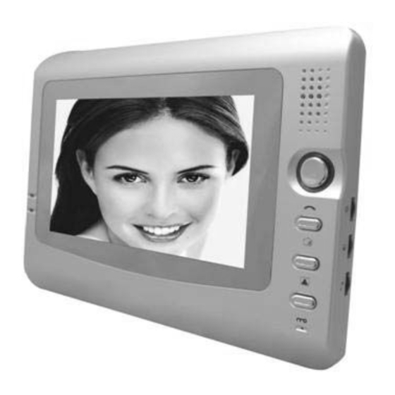
- Page 2 1. Monitor Unit Description The VDP311 system is a flexible and user-friendly system that allows a number of monitors to be used with a number of door units with cameras. The monitors allow visibility of the callers via the camera in the door units and, when used with the optional electronic lock, enable the resident to electronically open the door for the caller.
-
Page 3: Wall Mounting
2. Wall Mounting Fix the mounting bracket to the wall first using the fixing holes (2), then connect wiring and finally hook the monitor unit over the hooks (1) on the bracket 3. Electrical Connections The connections between the Door Unit (left) and the Monitor (right) are made using 4-wire cable as shown below. - Page 4 You can use any 4-core cable to make these connections, but screened and/or armoured cables are most secure. To connect additional monitors you will need to use 5-core cables to prevent interference between the monitors – only the monitor that accepts the call will be in communication with the caller. It is possible to use 4-cores for the signal and the screen for the ground connection.
- Page 5 4. Operation Caller at Door 1. Caller presses the Call button on the Door Camera 2. Both the monitor and the Door Camera will play the selected ring tone and the Activity LED will light on the monitor 3. The camera will turn on and the image of the caller will be displayed on the Monitor screen 4.
-
Page 6: Door Camera
5. Door Camera FRONT VIEW 1. Fixing hole (connects to mounting bracket) 2. Microphone 3. Camera 4. Light sensor (controls the infra-red) 5. Call button 6. Speaker 7. Fixing hole REAR VIEW 1. Fixing holes on bracket 2. Connection to main unit 3. -
Page 7: Technical Specification
6. Technical Specification Monitor dimensions: 230mm x 165mm x 35mm • Camera dimensions: 150mm x 120mm x 30mm • LCD on monitor: 7inch diagonal, TFT technology • Image sensor on camera: 1/3” CMOS, 1440 x 234 effective pixels • Audio and video communication between monitor and camera (video from •... - Page 8 The strike plate should be mounted on the door frame with the bolt passing centrally. The • roller, which helps release the bolt, passes directly over the bump at the top (or bottom if mounted on left) on the striker plate A 2-core wire is required to be fitted from the Door camera unit to the lock.
Need help?
Do you have a question about the VDP311 and is the answer not in the manual?
Questions and answers