Table of Contents
Advertisement
Quick Links
Download this manual
See also:
Instruction Manual
JVC SERVICE & ENGINEERING COMPANY OF AMERICA
DIVISION OF JVC AMERICAS CORP.
Head office
:
1700 Valley Road Wayne, New Jersey 07470-9976
:
10 New Maple Avenue Pine Brook, New Jersey 07058-9641
East Coast
:
705 Enterprise Street Aurora, Illinois 60504-8149
Midwest
:
5665 Corporate Avenue Cypress, California 90630-0024
West Coast
:
1500 Lakes Parkway Lawrenceville, Georgia 30043-5857
Atlanta
:
2969 Mapunapuna Place Honolulu, Hawaii 96819-2040
Hawaii
JVC CANADA INC.
Head office
:
21 Finchdene Square Scarborough, Ontario M1X 1A7
Montreal
:
16800 Rte Trans-Canadienne, Kirkland, Quebec H9H 5G7
:
Vancouver
13040 Worster Court Richmond, B.C. V6V 2B3
(973)317-5000
(973)396-1000
(630)851-7855
(714)229-8011
(770)339-2582
(808)833-5828
(416)293-1311
(514)871-1311
(604)270-1311
S40895-04
Printed in Japan
SERVICE MANUAL
DIGITAL VIDEO CAMERA
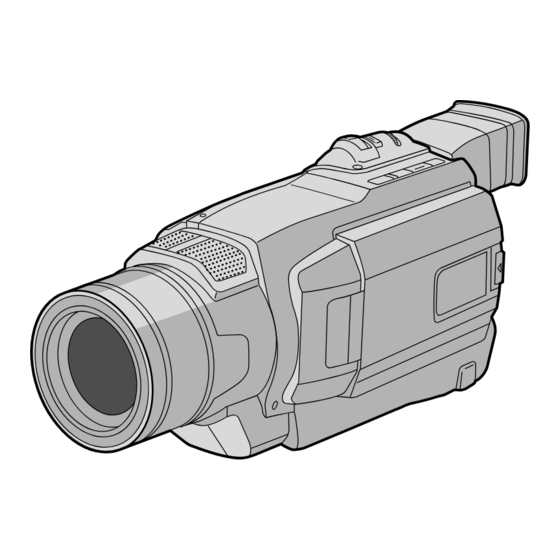
GR-DVL120U
SPECIFICATIONS
Camcorder
General
Power supply
: DC 11.0 V
(Using AC Adapter)
DC 7.2 V
(Using battery pack)
Power consumption
LCD monitor off, viewfinder on : Approx. 4.3 W
LCD monitor on, viewfinder off : Approx. 5.3 W
Dimensions (W x H x D)
: 83 mm x 94 mm x 223 mm (3-5/16" x 3-3/4" x 8-13/16")
(with the LCD monitor closed and the viewfinder
pushed down)
Weight
: Approx. 630 g (1.4 lbs)
Operating temperature
: 0°C to 40°C (32°F to 104°F)
Operating humidity
: 35% to 80%
Storage temperature
: –20°C to 50°C (–4°F to 122°F)
Pickup
: 1/4" CCD
Lens
: F 1.6, f = 3.9 mm to 62.4 mm, 16:1 power zoom lens
Filter diameter
: ø40.5 mm
LCD monitor
: 2.5" diagonally measured, LCD panel/TFT active matrix
system
Viewfinder
: Electronic viewfinder with 0.24" black/white LCD
Speaker
: Monaural
Digital Video Camera
Format
: DV format (SD mode)
Signal format
: NTSC standard
Recording/Playback format : Video: Digital component recording
: Audio: PCM digital recording, 32 kHz 4-channel (12-bit),
48 kHz 2-channel (16-bit)
Cassette
: Mini DV cassette
Tape speed
: SP: 18.8 mm/s
LP: 12.5 mm/s
Maximum recording time : SP: 80 min.
(using 80 min. cassette)
LP: 120 min.
This service manual is printed on 100% recycled paper.
COPYRIGHT © 2002 VICTOR COMPANY OF JAPAN, LTD.
Connectors
S-Video
: Y: 1 V (p-p), 75 Ω, analog
Output
C: 0.29 V (p-p), 75 Ω, analog
AV
: 1 V (p-p), 75 Ω, analog
Video output
Audio output
: 300 mV (rms), 1 kΩ, analog, stereo
DV
Output
: 4-pin, IEEE 1394 compliant
Input
: 4-pin, IEEE 1394 compliant
AC Adapter
Power requirement
U.S.A. and Canada
: AC 120 V`, 60 Hz
Other countries
: AC 110 V to 240 V`, 50 Hz/60 Hz
Output
: DC 11 V
, 1 A
Specifications shown are for SP mode unless otherwise indicated. E & O.E.
Design and specifications subject to change without notice.
No. 86671
March 2002
Advertisement
Table of Contents

Related Manuals for JVC GR-DVL120U


Summary of Contents for JVC GR-DVL120U
-
Page 1: Digital Video Camera
SERVICE MANUAL DIGITAL VIDEO CAMERA GR-DVL120U SPECIFICATIONS Connectors Camcorder S-Video JVC SERVICE & ENGINEERING COMPANY OF AMERICA General : Y: 1 V (p-p), 75 Ω, analog Output C: 0.29 V (p-p), 75 Ω, analog Power supply : DC 11.0 V (Using AC Adapter) DIVISION OF JVC AMERICAS CORP. -
Page 2: Table Of Contents
TABLE OF CONTENTS Section Title Page Section Title Page Important Safety Precautions 3. ELECTRICAL ADJUSTMENT 3.1 PRECAUTION ..............3-1 INSTRUCTIONS 3.2 SETUP ................. 3-2 1. DISASSEMBLY 1.1 BEFORE ASSEMBLY AND DISASSEMBLY ......1-1 1.1.1 Precautions ..............1-1 4. CHARTS AND DIAGRAMS 1.1.2 Assembly and disassembly .......... -
Page 3: Important Safety Precautions
Important Safety Precautions Prior to shipment from the factory, JVC products are strictly inspected to conform with the recognized product safety and electrical codes of the countries in which they are to be sold. However, in order to maintain such compliance, it is equally important to implement the following precautions when a set is being serviced. - Page 4 • Safety Check after Servicing Examine the area surrounding the repaired location for damage or deterioration. Observe that screws, parts and wires have been returned to original positions, Afterwards, perform the following tests and confirm the specified values in order to verify compliance with safety standards.
-
Page 5: Disassembly
SECTION 1 DISASSEMBLY 1.1 BEFORE ASSEMBLY AND DISASSEMBLY 1.1.4 Disconnection of connectors (Wires) 1.1.1 Precautions Connector Pull both ends of the connector in the arrow direction, re- 1. Be sure to remove the power supply unit prior to mount- move the lock and disconnect the flat wire. ing and soldering of parts. -
Page 6: Jigs And Tools Required For Disassembly, Assembly And Adjustment
1.2 JIGS AND TOOLS REQUIRED FOR DISASSEMBLY, 1.3 DISASSEMBLY/ASSEMBLY OF CABINET PARTS ASSEMBLY AND ADJUSTMENT AND BOARD ASSEMBLY 1.2.1 Tools required for adjustments 1.3.1 Disassembly flow chart This flowchart indicates the disassembly step for the cabi- Torque driver YTU94088 YTU94088-003 net parts and board assembly in order to gain access to item(s) to be serviced. -
Page 7: Disassembly Method
1.3.2 Disassembly method Note: Remove the parts marked in STEP CONN. Fig.No. POINT NOTE PART CONNECTOR Pin No. ⇔ COVER(ZOOM) Fig.1-3-1 (S1a),(S1b),2(L1a),2(L1b ) MAIN CN101 MONITOR CN761 ASSY CN106 ← → MIC MAIN — UPPER CASE ASSY Fig.1-3-2 4(S2a),3(S2b),(L2),(S2c) NOTE2 ⇔... - Page 8 Fig. 1-3-1 (DC JACK) NOTE (BOTTOM SIDE) (REAR SIDE) Fig. 1-3-2...
- Page 9 NOTE NOTE Fig. 1-3-3 BRACKET (OP) ASSY Fig. 1-3-4...
- Page 10 : 0.196 N m (2.0 kgf • • Fig. 1-3-5 NOTE Fig. 1-3-6...
- Page 11 Fig. 1-3-7 SHIELD PLATE NOTE EJECT SW NOTE Fig. 1-3-8 Fig. 1-3-9...
- Page 12 NOTE NOTE Fig. 1-3-10 PLATE (SPK) NOTE NOTE ∗ COVER (HINGE) ∗ ∗ : 0.147 N m (1.5 kgf • • Fig. 1-3-11...
-
Page 13: Monitor Assembly
MONITOR ASSEMBLY Note: The shape of the monitor assembly varies by the size 3. Remove the screw (5), unplug the FPC from the connec- of the LCD screen. tor b , and then remove the LCD BL board assembly, DIF sheet and bracket (FRM2) in that order. For the 2.5”-type LCD, refer to Fig. -
Page 14: E. Vf Assembly
E. VF ASSEMBLY 1.5.1 Disassembly/assembly of E.VF assembly (for the B/W VF) 5. Remove the screw (8) and the remove the CAP (VF). 1. Remove the EYE CUP. 6. Remove the FPC from the CASE A (VF) so that the CASE 2. -
Page 15: Disassembly/Assembly Of 5Op Block Assembly/Ccd Board Assembly
1.6 DISASSEMBLY/ASSEMBLY OF 5OP BLOCK ASSEMBLY/CCD BOARD ASSEMBLY 1.6.1 Precautions 1.6.3 How to assemble CCD base assembly and CCD board assembly 1. Take care in handling the CCD image sensor, optical LPF and lens components when performing maintenance 1. Install the optical LPF with the spacer rubber attached etc., especially with regard to surface contamination, at- to its CCD side in the OP block assembly. -
Page 16: Emergency Display
1.7 EMERGENCY DISPLAY Whenever some abnormal signal is input to the syscon CPU, Example (in case of the error number E01): an error number (E01, as an example) is displayed on the LCD monitor or (in the electronic view finder). In every error status, such the message as shown below alternately appear over and over. -
Page 17: Service Note
1.8 SERVICE NOTE 1-13... -
Page 18: Mechanism Adjustment
SECTION 2 MECHANISM ADJUSTMENT 2.1 PRELIMINARY REMARKS ON ADJUSTMENT AND (3) The symbol (T or B)appearing in this column shows the REPAIR side which the objective part is mounted on. T =the upper side, B =the lower side 2.1.1 Precautions (4) Symbols appearing in this column indicate drawing 1. -
Page 19: Jigs And Tools Required For Disassembly, Assembly And Adjustment
2.2 JIGS AND TOOLS REQUIRED FOR DISASSEMBLY, ASSEMBLY AND ADJUSTMENT 2.2.1 Tools required for adjustments 1. Torque driver Torque driver YTU94088 YTU94088-003 Be sure to use to fastening the mechanism and exterior parts because those parts must strictly be controlled for tightening torque. -
Page 20: Disassembly/Assembly Of Mechanism Assembly
2.3 DISASSEMBLY/ASSEMBLY OF MECHANISM <SUB CAM GEAR> ASSEMBLY 2.3.1 General statement The mechanism should generally be disassembled/assem- bled in the EJECT mode (ASSEMBLY mode). (Refer to Fig. 2-3-1.) TOP VIEW BOTTOM VIEW However, when the mechanism is removed from the main body, it is set in the STOP mode. -
Page 21: Mechanism Timing Chart
2.3.3 Mechanism timing chart MODE EJECT C IN SHORT FF STOP PLAY PARTS MAIN CAM (ø10.4) 31.7 45.6 49.5 74.04 129.5 156.6 169.2 211.5 280.3 SUB CAM (ø11) 43.1 46.8 122.5 148.1 ENCODER (ø10) 47.4 51.5 134.7 162.9 291.5 ROTARY ENCODER CAM SW SLIDE END... -
Page 22: Disassembly/Assembly Of Mechanism Assembly
2.4 DISASSEMBLY/ASSEMBLY OF MECHANISM ASSEMBLY 2.4.1 Follow chart 1. Configuration Mechanism assembly Cassette housing assembly Slide deck assembly Main deck assembly Fig. 2-4-1 2. Procedures for disassembly Mechanism assembly Cassette housing assembly Slide deck assembly Main deck assembly Fig. 2-4-2... - Page 23 3. Disassembling procedure table PART NAME FIG. POINT NOTE REMARKS A Cassette housing assembly Fig. 2-4-5 3(S1),(L1a)-(L1d) 1a, 1b, 1c, 1d Adjustment Reel disk (SUP) assembly Fig. 2-4-6 (W2) 2a, 2b Reel disk (TU) assembly Fig. 2-4-6 (W2) 2a, 2b Reel cover assembly Fig.
- Page 24 < TOP VIEW > 4b 11b 11a Main deck assembly Slide deck assembly 7b 7a 7d 7e 9c 3c 3b 7h 2b Fig. 2-4-3 < BOTTOM VIEW > Main deck assembly Slide deck assembly Fig. 2-4-4...
-
Page 25: Disassembly/Assembly
2.4.2 Disassembly/assembly Note 1a: <STOP mode> Shift the mechanism mode 1. A Cassette housing assembly from the STOP mode to the EJECT mode. Cassette Note 1b: housing Reassemble the cassette (L1b) assembly housing assembly to the (S1) mechanism as the cancel lever is moved in the direc- tion of the arrow. - Page 26 3. 3a Tension arm assembly/ 3b Release guide assembly 3c Idler arm assembly/ 3d Guide arm assembly 3e Pinch roller arm assembly Note 3a: When removing the reel cover assembly, pay heed to re- lease guide assembly and guide arm assembly. For the (W3a) guide arm assembly is just inserted into the slide deck as- sembly from the upside and it is apt to come off after the...
- Page 27 5. 5a Guide roller (S) assembly/ 5b Rail assembly Note 5a: When reassembling, insert the tip Guide roller of the guide roller with the coil (s) assembly spring put on it into the hole on the main deck. Tighten the guide roller by about 6 turns so that the Note 5a (P5)
- Page 28 Note 7a: 7. 7a Loading brake assembly/ 7b Guide pin (S) Don’t remove these parts unreasonably. If they are removed 7c Pad arm assembly/ 7d Slide guide plate assembly for some reason, be very careful not to lose them. 7e Collar/ 7f Collar/ 7g Sub brake assembly 7h Control plate assembly Note 7b: When reinstalling the sub brake assembly, set the control...
- Page 29 9. 9a Loading guide/ 9b Timing belt 9c Center gear assembly/ 9d Motor bracket assembly 9e Worm wheel/ 9f Gear holder Note 9a: Note 9b Note 9a Carefully handle the DEW sensor. (Don’t touch the sensor surface in particular.) Note 9b: When engaging the timing belt, make sure that it securely (S9) engages with the gears of both the center gear assembly and...
- Page 30 11. 11a Catcher (T) assembly/ 11b Capstan motor 11c Charge arm assembly/ 11d Sub cam gear 11e PWB holder Note 11: The following figure shows how to put the charge arm as- sembly and sub cam gear assembly together. (S11) (S11) Note 11 (W11)
-
Page 31: List Of Procedures For Disassembly
2.4.3 List of procedures for disassembly Cassette housing assembly (P5) (L1b) (S9) (W5a) (S9) (W5b) (W5a) (W3b) (S1) (W5a) (W10b) (L1d) (L1a) (S4) (S4) (S4) (S1) (L1c) (S1) (S11) (W10a) (S10) (S11) (S10) (W10a) (S11) (S9) (S11) (W9) (W4) (P4b) (P4a) (S9) (W7) -
Page 32: Checkup And Adjustment Of Mechanism Phase
2.5 CHECKUP AND ADJUSTMENT OF MECHANISM PHASE <Connect gear> (Note 2) Set the connect gear so <Rotary encoder> that its locating hole meets Set the “I” of the rotary the hole on the main deck part at the tapped hole assembly. -
Page 33: Mechanism Adjustments
2.6 MECHANISM ADJUSTMENTS 2.6.1 Assembling slide deck assembly and main deck assembly œ Œ Fig. 2-6-1 Assembling procedure 1. Loosen the screw A. 2. Set the mechanism in the PLAY mode. (Refer to “2.3.2 Explanation of mechanism mode”.) 3. Press the end face B of the slide deck assembly (reel disk side) and the end face C of the main deck assem- bly (drum assembly side) with uniform force so that the two assemblies are tightly pressed to each other. -
Page 34: Locating Tension Pole
2.6.2 Locating tension pole <PLAY mode> Fig. 2-6-2 Locating procedure 1. Enter the mechanism assembly into the PLAY mode. (Refer to “2.3.2 Explanation of mechanism mode”.) 2. When the “ ” part is positioned down, make sure that the part “a” of the tension arm assembly is located within the range of “b”. -
Page 35: Service Note
2.7 SERVICE NOTE Use the following chart to manage mechanism parts that are removed for disassembling the mechanism. Cassette housing assembly S1×3 Reel disk (SUP) assembly Reel cover assembly W2×1 Reel disk (TU) assembly W2×1 S2b×1 S2a×2 W2×1 Guide arm Tension arm Pinch roller arm Release guide... - Page 36 Slide deck assembly Loading Slide guide Guide pin Pad arm brake plate assembly assembly assembly W7×1 P7a×1 S7a×1 W7×1 P7b×1 S7b×1 Control Collar Collar Sub brake plate assembly assembly W7×1 P7c×1 W7×2 P7d×1 W6×1 Main deck assembly Slide lever Tension lever Brake control assembly assembly...
-
Page 37: Compatibility Adjustment
2.8 COMPATIBILITY ADJUSTMENT 2.8.1 Jig connector cable connection Remove one screw (1) first and the cover (JIG) next. Jig connector cable (YTU93082G) CN105 Cover(JIG) JIG BOARD Fig. 2-8-1 Jig connector cable connection MAIN JIG BOARD CN105 (PIN NO.) (LABEL) AL_3VSYS AL_3VSYS DISCRI 10 DRST... -
Page 38: Tape Pattern Check
2.8.2 Tape pattern check (1) Play back the compatibility adjustment tape. (2) While triggering the MAIN CN105-16PIN (HID1), ob- CN105 serve the waveform of CN105-15PIN (ENV_OUT). (ENV_OUT) (3) Confirm that the waveform is free from remarkable level-down, and entirely parallel and straight. Moreover, perform the following adjustment as re- CN105 quired. -
Page 39: Electrical Adjustment
SECTION 3 ELECTRICAL ADJUSTMENT 3.1 PRECAUTION 3. Tools required for adjustments 1. Precaution Torque driver Both the camera and deck sections of this model needs a YTU94088 YTU94088-003 personal computer for adjustment except simple adjustment with potentiometers. If some of the following parts is replaced for repair or other reason, the repaired set must be adjusted with a personal computer. -
Page 40: Setup
Torque driver Alignment tape Be sure to use to fastening the mechanism and exte- To be used for check and adjustment of interchange- rior parts because those parts must strictly be control- ability of the mechanism. led for tightening torque. 10.
Need help?
Do you have a question about the GR-DVL120U and is the answer not in the manual?
Questions and answers