Aprilaire 400 SERIES Manual
Hide thumbs
Also See for 400 SERIES:
- User manual ,
- Owner's manual (20 pages) ,
- Dealer parts list (8 pages)
Table of Contents
Advertisement
Quick Links
RE D COMPLETE S FETY INSTRUCTIONS
This product must be installed by a qualified heating and air conditioning contractor. Failure to do so could result in serious injury from electrical shock.
Proper humidification and humidity control also requires that the home be constructed in accordance with local codes and good building practices.
WARNING
ELECTRICAL SHOCK HAZARD.
1.
Disconnect electrical power to the
furnace before starting installation.
Failure to do so could result in
serious injury from electrical shock.
SHARP EDGES HAZARD.
2.
Sharp
edges may cause serious injury from
cuts. Use care when making plenum
openings and handling ductwork.
RISK OF SCALDING.
3.
Water
temperature over 125°F can cause
severe burns and scald instantly.
Shut off the hot water supply before
disconnecting or tapping into any
hot water supply line.
RECOMMENDED WIRING DIAGRAM
(SEE STEP 7 ON BACK AND "HUMIDIFIER CONTROL SAFETY AND INSTALLATION INSTRUCTIONS" FOR DETAILED WIRING INSTRUCTIONS)
Model 400
DIGITAL HUMIDIFIER CONTROL
NORTH, EAST
OR WEST SIDE
OF HOME
OUTDOOR TEMPERATURE
SENSOR FOR
AUTOMATIC MODE
R
ABOVE EXPECTED
C
SNOW LINE
G
Y
W
THERMOSTAT
90-1513
IMPORTANT
Model 400M
USE 120 VAC POWER SOURCE OTHER THAN FURNACE MOTOR
CIRCUIT. HOWEVER, THE TRANSFORMER CAN BE POWERED
MANUAL CONTROL
OFF THE HOT 120 VAC LINE BEFORE IT ENTERS THE FURNACE.
• DO NOT WIRE TRANSFORMER INTO FURNACE BLOWER CIRCUIT.
24 VAC FURNACE ACCESSORY
TERMINALS OR TRANSFORMER
(10VA MINIMUM)
COMMON
HI
LO
FURNACE
BLOWER MOTOR
RESEARCH PRODUCTS CORPORATION • P.O. BOX 1467 • MADISON, WI 53701-1467 • CALL 800/334-6011 • FAX 608/257-4357
ND INST LL TION TEMPL TE BEFORE ST RTING INST LL TION
ATTENTION INSTALLER:
This product must be installed in compliance with all local, state and federal codes.
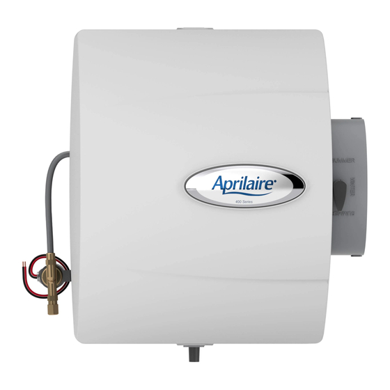
MODEL 400 SERIES HUMIDIFIER
RISK OF PROPERTY AND EQUIPMENT DAMAGE.
1. Do not install humidifier where freezing temperatures
could occur. The water line could freeze and crack
causing water damage to the home.
2. Do not install humidifier or bypass connection on the
furnace jacket.
3. Do not install humidifier or bypass connection on a
plenum face where the blanked off ends of the cooling
coil will restrict air movement through the humidifier.
4. Do not set humidity level above recommended or to
recommended level if condensation exists on inside
windows of any unheated space, as condensation
damage may result. Excess humidity can cause
moisture accumulation which can allow the possibility
for mold growth in the home.
ADHC TERMINAL STRIP
POWER
INPUTS
R
C
A
B
ODT
W
G
H
R
C
G
Y
W
FURNACE
TRANSFORMER PROVIDED WITH HUMIDIFIER
MODEL 50
CURRENT SENSING RELAY
(IF REQUIRED)
IMPORTANT
WHEN MODEL 50 CURRENT
SENSING RELAY IS USED:
• WIRE MODEL 50 CURRENT
SENSING RELAY INTO 24 VAC
HUMIDIFIER CONTROL
CIRCUIT ONLY! DO NOT
INSTALL IN TRANSFORMER
PRIMARY CIRCUIT.
CAUTION
5. Do not connect Model 400 or 400M
transformer to blower motor wiring. Premature
component failure may result.
6. When installing Humidifier Control on
downflow furnace, ensure blower continues to
run after a heat call is satisfied to eliminate
high temperatures from damaging the Control.
7. Do not install humidifier where water pressure
exceeds 125 psi, since damage to the
humidifier may result. Follow codes in effect
concerning pressure reduction.
8. Do not install humidifier on systems with
greater than 0.4 in. wg pressure differential
between supply and return plenums.
OUTPUTS
H
Gf
WHITE WIRES
YELLOW WIRES
110 VAC
CONNECT TO
HOT WATER SUPPLY
CONTINUOUSLY POWERED 24 VAC
SHUT-OFF
(SADDLE VALVE)
WATER SUPPLY
YELLOW
WIRES
CONNECT OVERFLOW TUBE HERE
SPECIFICATIONS
HUMIDIFIER DIMENSIONS
Width
(including solenoid valve):
Height
BYPASS DUCT OPENING
24 VAC-60 Hz, 0.5 AMP
INSTALLATION
OPTIONS
The Model 400 and 400M Aprilaire can be
installed on either the supply or return
plenum of a forced air handling system and is
easily reversible for installation with right
hand or left hand bypass duct connections.
The humidifier dimensions and serviceability
must be considered when selecting the best
location for the humidifier. Here are
2 examples of many types of installations.
Upflow
RETURN
CONNECT
OVERFLOW
TUBE HERE
Horizontal
RETURN
WHITE
WIRES
When installing Model 400 humidifier on a
heat pump system, the evaporative capacity
will be reduced due to air temperatures
below 120°F. Plumbing to hot water partially
90-1399
offsets the reduction.
15
3
⁄
"
8
15
3
⁄
"
(including drain spud):
4
Depth
10
1
⁄
"
:
4
6" diameter
PLENUM OPENING
10"W x 12
3
⁄
"H
4
ELECTRICAL DATA
S
SUPPLY
S
SUPPLY
90-1079
NOTE
Advertisement
Table of Contents

Subscribe to Our Youtube Channel
Related Manuals for Aprilaire 400 SERIES


Summary of Contents for Aprilaire 400 SERIES
-
Page 1: Specifications
RECOMMENDED WIRING DIAGRAM OPTIONS (SEE STEP 7 ON BACK AND “HUMIDIFIER CONTROL SAFETY AND INSTALLATION INSTRUCTIONS” FOR DETAILED WIRING INSTRUCTIONS) The Model 400 and 400M Aprilaire can be Model 400 installed on either the supply or return plenum of a forced air handling system and is... -
Page 2: Parts List
– TOP – READ REVERSE SIDE FIRST! READ REVERSE SIDE FIRST! RE D COMPLETE S FETY INSTRUCTIONS ND INST LL TION TEMPL TE BEFORE ST RTING INST LL TION Figure 1 Figure 2 Figure 3 FURNISHED ITEMS Built-in bypass damper 24 VAC Transformer Digital Humidifier Control (Model 400) Manual Humidifier Control (Model 400M)
Need help?
Do you have a question about the 400 SERIES and is the answer not in the manual?
Questions and answers