Table of Contents
Advertisement
Manufactured under license from Dolby Laboratories Licens-
ing Corporation.
DOLBY, the double-D symbol
trademarks of Dolby Laboratories Licensing Corporation.
IMPORTANT SERVICE NOTES (For U.S.A. Only) ........................................................................................................... 2
SPECIFICATIONS .............................................................................................................................................................. 3
NAMES OF PARTS ........................................................................................................................................................... 4
OPERATION MANUAL ...................................................................................................................................................... 7
QUICK GUIDE ................................................................................................................................................................... 8
DISASSEMBLY .................................................................................................................................................................. 9
REMOVING AND REINSTALLING THE MAIN PARTS ................................................................................................... 12
ADJUSTMENT ................................................................................................................................................................. 13
NOTES ON SCHEMATIC DIAGRAM .............................................................................................................................. 16
BLOCK DIAGRAM ........................................................................................................................................................... 17
SCHEMATIC DIAGRAM / WIRING SIDE OF P.W.BOARD .............................................................................................. 20
VOLTAGE ........................................................................................................................................................................ 40
WAVEFORMS OF CD CIRCUIT ...................................................................................................................................... 41
TROUBLESHOOTING (CD SECTION) ........................................................................................................................... 42
FUNCTION TABLE OF IC ................................................................................................................................................ 47
FL DISPLAY ...................................................................................................................................................................... 54
REPLACEMENT PARTS LIST/EXPLODED VIEW
PACKING OF THE SET (For U.S.A. Only)
SERVICE MANUAL
and "PRO LOGIC" are
CONTENTS
SHARP CORPORATION
- 1 -
CD-PC672
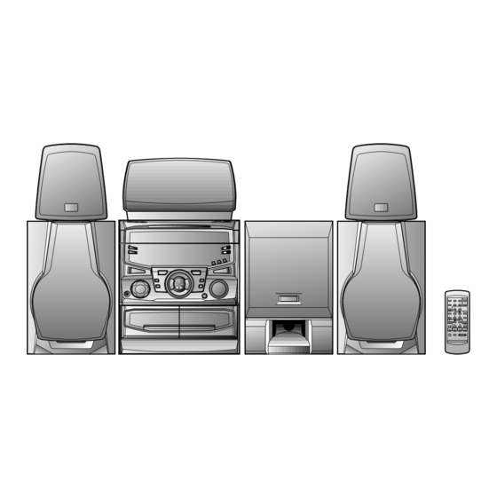
CD-PC672 mini component system consisting of CD-PC672 (main
unit),
CP-C672 (front speakers), CP-SW672 (sub woofer),
GBOXS0022AWM1 (center speaker) and GBOXS0023AWM1 (rear
speaker).
• In the interests of user-safety the set should be restored to its
original condition and only parts identical to those specified be
used.
This document has been published to be used
for after sales service only.
The contents are subject to change without notice.
CD-PC672
No. S4915CDPC672/
Page
Advertisement
Table of Contents

Related Manuals for Sharp CD-PC672


Summary of Contents for Sharp CD-PC672
-
Page 1: Table Of Contents
CD-PC672 SERVICE MANUAL No. S4915CDPC672/ CD-PC672 CD-PC672 mini component system consisting of CD-PC672 (main unit), CP-C672 (front speakers), CP-SW672 (sub woofer), GBOXS0022AWM1 (center speaker) and GBOXS0023AWM1 (rear speaker). • In the interests of user-safety the set should be restored to its original condition and only parts identical to those specified be used. -
Page 2: Important Service Notes (For U.s.a. Only)
CD-PC672 FOR A COMPLETE DESCRIPTION OF THE OPERATION OF THIS UNIT, PLEASE REFER TO THE OPERATION MANUAL. IMPORTANT SERVICE NOTES (For U.S.A. Only) BEFORE RETURNING THE AUDIO PRODUCT (Fire & Shock Hazard) Before returning the audio product to the user, perform the following safety checks. -
Page 3: Specifications
CD-PC672 SPECIFICATIONS CD-PC672 Front speaker section General Power source: AC 120 V, 60 Hz CP-C672 Power consumption: Stand-by; 0.3 W Type: 2-way 5-1/4" (13 cm) woofer Power on; 150 W and 2" (5 cm) tweeter type Dimensions: Width; 10-5/8" (270 mm) -
Page 4: Names Of Parts
CD-PC672 NAMES OF PARTS CD-PC672 Front panel Disc Number Selector Buttons Disc Tray Multi Indicator Disc Skip Button Open/Close Button Extra Bass Indicator FM Stereo Mode Indicator FM Stereo Indicator (CD) Repeat Indicator (CD) Play Indicator (CD) Pause Indicator 12 13... - Page 5 CD-PC672 Rear panel CD Digital Output Socket AC Power Lead FM/AM Loop Aerial Socket Video/Auxiliary (Audio Signal) Input Sockets Rear Speaker Terminals Centre Speaker Terminals Front Speaker Terminals Sub Woofer Terminals 5 6 7 8 CP-C672 Front speakers Tweeter Woofer...
-
Page 6: Tuner Control Section
CD-PC672 CD-PC672 Remote control Remote Control Transmitter LED Surround Level Buttons Centre Level Buttons Dolby Pro Logic Button Centre Mode Button Test Tone Button Balance Control Buttons Tuner control section Preset Up/Down Buttons 11 12 CD control section Memory Button... -
Page 7: Operation Manual
CD-PC672 OPERATION MANUAL – 7 –... - Page 8 CD-PC672 – 8 –...
-
Page 9: Disassembly
CD-PC672 DISASSEMBLY CD-PC672 Caution on Disassembly Follow the below-mentioned notes when disassembling Top Cabinet the unit and reassembling it, to keep it safe and ensure excellent performance: (A1)x2 1. Take cassette tape and compact disc out of the unit. ø3x12mm 2. - Page 10 CD-PC672 Front Panel ( K1 ) x1 ø3 x10mm ( K2 ) x1 Washer (E1)x2 (F2)x2 (F3)x5 Turntable Push Push (E2)x1 2 Pull (F2)x2 (E3)x1 POWER Headphoens POWER PWB Disc Tray ( L1 ) x1 ø3 x10mm (F1)x3 ( L2 ) x1 ø3x10mm...
- Page 11 CD-PC672 CP-C672 CP-C672 PROCEDURE STEP REMOVAL FIGURE Front Speaker 1. Net ......(A1) x1 11-1 2. Front Panel .... (A2) x1 3. Screw ..... (A3) x4 4. Tip ......(A4) x2 Front Panel (A2)x1 5. Screw ..... (A5) x2 6. Tip ......(A6) x2...
-
Page 12: Removing And Reinstalling The Main Parts
CD-PC672 REMOVING AND REINSTALLING THE MAIN PARTS CD MECHANISM SECTION Loading / Up Perform steps 1, 2, 3 and 10-14 of the disassembly method to remove the CD mechanism. / Down Motor Motor How to remove the loading motor (See Fig. 12-1) 1. -
Page 13: Notes On Schematic Diagram
CD-PC672 NOTES ON SCHEMATIC DIAGRAM • The indicated voltage in each section is the one measured • Resistor: by Digital Multimeter between such a section and the chas- To differentiate the units of resistors, such symbol as K and sis with no signal given. -
Page 14: Block Diagram
CD-PC672 TO MAIN SECTION 9 8 7 6 5 4 3 2 1 CNS10 TO MAIN SECTION (TO IC601) +7.3V (B1) 9 8 7 6 5 4 3 2 1 3 2 1 4 5 6 CNP11 CNP99 CNP10 BI1A BI1B +4.3V... -
Page 15: Voltage
CD-PC672 SWM3 FOOL PROOF SWM4 F.A.S AM LOOP SOLM1 ANTENNA ANTENNA SOLENOID SWM5 IC301 FM IF TAPE MO TA7358AP CF301 L301 T301 FM FRONT END FM B.P.F VR381 AM IF MPX VCO ADJ T381 T382 CF351 MONO/ST FM OSC FM IF IN... - Page 16 CD-PC672 FL701 DISPLAY Q702 1 2 3 4 37 38 39 Q703 TAPE MOTOR Q705 Q706 Q707 IC701 IX0310AW SYSTEM CONTROL MICROCOMPUTER AVDD RX701 UNSWITCH MEMORY BACK UP 9 8 7 6 5 4 3 2 1 TO CD SECTION...
-
Page 17: Pickup Unit
CD-PC672 47/16 0.01 0.33/50 0.01 1/50 2SA1318 64 63 61 60 55 54 53 52 51 50 49 LA9241M VCC1 CNS1B CNS1A SERVO AMP. – FIN2 – FIN1 EFBAL – – FOSTA – DGND TOSTA – 2FREQ CNP1 0.1/50 LASER –... - Page 18 CD-PC672 0.01 64 63 60 59 58 57 56 55 54 53 52 51 50 EFLG SBSY MICRO-COM SUB-CODE INTERFACE DEF1 XVSS 3.3M X-TAL XOUT GENERATOR 2KX8 0.047 VVSS XVDD LC78622N ISET MUTER R-CH 0.047 A_GND ERROR RVDD CLOCK CD_RCH...
- Page 19 CD-PC672 TO CD SERVO PWB P21 12-C CNP11 TO DECK SECTION TO TUNER SECTION 1 2 3 4 5 6 P27 12-F P25 12-B CNS11 BI401 2 3 4 5 6 7 8 9 11 12 13 14 15 16 17 18 19 20 21...
- Page 20 CD-PC672 CNS11 BI401 FM SIGNAL PLAYBACK SIGNAL RECORD SIGNAL CD SIGNAL L-CH R403 C461 R401 1.8K 390P VIDEO_1 R404 C462 R402 390P 1.8K C448 R-CH 2.2/50 R405 R422 L-CH 2.7K C463 R407 390P 1.8K VIDEO_2 C447 R406 R408 C464 2.2/50 390P 1.8K...
- Page 21 CD-PC672 PLAYBACK SIGNAL RECORD SIGNAL R174 150(1/2W) Q110 C109 R114 KRC104 M C153 0.047 100/16 3.4V R113 9.3V 3.4V Q109 TAPE1 Q111 9.3V KTA1266 GR KRC104 M PLAYBACK HEAD R112 C102 0.001 R120 R-CH C120 560P TAPE1_R R102 C118 0.033...
- Page 22 CD-PC672 TAPE_R T1/T2 REC_MUTE R182 220K REC_R Q121 REC_L R181 KTC3199 GR 220K R154 R153 TAPE_L 0.7V 0.7V BIAS Q122 KTC3199 GR D102 DS1SS133 D_GND C120 A_12V D101 560P A_GND DS1SS133 R126 5.6K R124 M_GND 3.9K R158 C122 330(1/4W) C134...
- Page 23 CD-PC672 FM SIGNAL AM SIGNAL L301 B.P.S. IC301 TA7358AP FM FRONT END C303 10P(CH) R301 C304 R316 FM BAND 0.01 COVERAGE fL T301 VD302 FM OSC VARIABLE CAP C309 R309 D391 0.001 DS1SS133 C313 (CH) FM IF T302 R311 CF301...
- Page 24 CD-PC672 Q382 KTC3199 GR C383 R398 R397 220P TP302 C388 C382 R382 0.0015 0.0022 1.5K C385 T381 3.3/50 R383 R384 FM DET 1.2K 24 23 22 21 20 19 15 14 VR381 FM DET DET OUT 6.8K IC303 FM/AM IF MPX.
- Page 25 CD-PC672 FL701 DISPLAY 1 2 3 4 5 6 7 8 9 10 11 12 13 14 15 16 17 18 19 20 21 22 23 24 25 26 27 28 29 30 31 32 Q707 KTC3199 GR R701 R702...
- Page 26 CD-PC672 C716 R781 47/16 27 28 29 30 31 32 33 34 35 36 37 38 39 C717 0.022 DATA CLOCK R782 1K LED721 C706 R793 1K LED711 R783 1K LED720 1/50 LED719 LED712 R792 1K R784 1K 91 92 93 94 95 96 97 98 99 100...
- Page 27 CD-PC672 IC901 3 Ch STK4084B POWER AMP. FM SIGNAL C926 C915 C923 R912 C929 C916 C904 C907 C911 10/35 10/35 100/50 R917 R930 R931 C912 R918 R927 100/50 R961 C917 R913 C901 47/50 C918 R905 1/50 47/50 C903 1/50 R907 1K...
- Page 28 CD-PC672 R969 120(1/2W) M901 FAN MOTOR D903 C978 R968 DS1SS133 47/50 IC99 BI99 R965 D909 Q907 C979 Q905 4.7K DS1SS133 KRC107 M 10/35 KTC3199 GR 2.2mmH R931 F903 RL902 4A/125V F901 0.022 100/10 4A/125V DIGITAL OUTPUT PWB-C2 F902 4A/125V C935...
- Page 29 CD-PC672 MAIN PWB-A1 C305 Q351 D382 R355 IC301 C303 R354 R358 1 2 3 4 5 6 7 8 9 L301 R356 10 11 R357 C304 R314 R323 CNP301 3 2 1 T302 L312 IC302 C356 C353 C321 C314 C308...
- Page 30 CD-PC672 R160 R167 Q128 B C E Q122 C118 C150 C140 R168 L104 R111 C105 13 15 R158 C142 C151 CNP102 D102 D101 IC101 C108 R118 R113 R108 C109 R107 R114 C107 Q110 R110 R109 R117 Q126 Q107 R141 C115...
- Page 31 CD-PC672 TO TA TO POWER PWB TO MAIN PWB P36 1-G P33 12-D CNP806 CNP502 CNS806 3 4 5 6 7 DISPLAY PWB-A2 FFC701 SW715 CNP701 VIDEO LED721 R782 BI703 D722 RD13 LED719 Q702 C705 R783 MEMORY/SET SW712 LED720 SW716...
- Page 32 CD-PC672 TO TAPE MECHANISM PWB TO CD SERVO PWB P38 5-A P39 11-E CNPM1 CNS12 CNS12 CNSM1 3 4 5 6 7 8 BI701 VR702 SUB WOOFER VOLUME VOLUME LED723 D716 LED724 BI702 SW724 Q703 TUNING DOWN E C B...
- Page 33 CD-PC672 FROM POWER TRANSFORMER P38 2-C CNS80 CNS805 CNP805 C816 IC803 Q802 F802 F803 5A/125V 5A/125V D810 FROM POWER C818 TRANSFORMER P38 1-C C817 CNS802 R808 C807 POWER PWB-C1 CNP802 D801 C812 C805 C806 D808 C811 D906 C944 C949 Q801...
- Page 34 CD-PC672 AC POWER SUPPLY CORD(249) AC 120V, 60Hz M901 FAN MOTOR (251) (251) CNS804 PT802 D811 IC803 Q802 POWER TRANSFORMAER CNP801 FROM POWER RL801 TRANSFORMER P38 1-E C818 CNS801 R808 D825 Q905 R966 R967 C979 C909 D903 C978 CNP804 R910...
- Page 35 CD-PC672 TO DISPLAY PWB SWM3 P35 7-A F. P. (260-9) CNSM1 CNPM1 FWM2 FWM1 PHM1 SWM4 CNPM2 F. A. S (260-10) SOLM1 TAPE MECHANISM SOLENOID (260-8) PWB-F SWM5 CAM(260-11) TAPE MOTOR(260-7) TAPE MECHANISM ASSEMBLY TAPE 2 TAPE 1 RECORD/PLAYBACK ERASE HEAD(260-5)
- Page 36 CD-PC672 CD SERVO PWB-B CNP1 E C B CNP2 CNP3 30 35 32 33 3035 BI1-B 32 33 B C E BI1-A CNP99 CNP12 CNP11 CNS11 CNS12 FROM MAIN PWB FROM DISPLAY PWB P32 1-D P35 8-A IC99 CNS99 DIGITAL OUTPUT PWB-C2...
- Page 37 CD-PC672 VOLTAGE IC301 IC302 IC303 IC701 PIN VOLTAGE NO. VOLTAGE NO. VOLTAGE NO. VOLTAGE NO. VOLTAGE NO. VOLTAGE NO. VOLTAGE VOLTAGE 2.4V 2.5V 0.9V (0V) 2.5V (2.5V) 1.6V (1.6V) 4.7V 4.7V 2.4V 2.6V 4.7V 1.6V (0V) 0V (0V) 1.6V (1.6V) 2.5V...
-
Page 38: Waveforms Of Cd Circuit
CD-PC672 WAVEFORMS OF CD CIRCUIT STOP PLAY FOCUS SERCH 0.5ms 0.50 V 10.0 V IC1 20 F.E 0.5ms 10.0 V 0.5ms 5.0 V 0.50 V IC1 54 DRF 0.5ms 1.00 V PLAY 0.5ms NORMAL DISC 1.00 V TN0=01 20ms 1.00 V 0.5ms... -
Page 39: Troubleshooting (Cd Section)
CD-PC672 TROUBLESHOOTING (CD SECTION) When the CD does not function When the CD section does not operate when the objective lens of the optical pickup is dirty, this section may not operate. Clean the objective lens, and check the playback operation. When this section does not operate even after the above step is taken, check the following items. - Page 40 CD-PC672 • When the turntable fails to stop. Is from 5 V till 2.5V down pulse (approx. 300 ms) Check the SWM3 and the wiring from the IC701 pin 21 to the 2.5V SWM3. input into the IC701 pin 21 when the turntable is rotating?
- Page 41 CD-PC672 • When the CD tray fails to open or close. Check the OPEN CLOSE SW and the wiring from the IC701 Is there following voltage input in specific state of IC701 pin 19? pin 19 to the OPEN CLOSE SW.
- Page 42 CD-PC672 • Playback can only be performed when a disc is loaded. Check the laser diode driver. Is the Focus servo active? (Can you hear it working?) Check the area around IC1(16) - (21) (focus servo circuit). If the disc is not turning, the DRF Does the DRF signal change from "L"...
- Page 43 CD-PC672 • Checking the spin system. Play operation is performed without disc. The turntable rotates a little. The spin driver circuit is normal. Check the periphery of IC1 pins 23 to 27, pin 39, and pin 40, IC2 The turntable fails to rotate or rotates at high speed.
-
Page 44: Function Table Of Ic
CD-PC672 FUNCTION TABLE OF IC IC1 VHiLA9241M/-1: Servo Amp. (LA9241M) (1/2) Function Port Name Pin No. FIN2 Connection pin for photodiode of pickup. RF signal is generated through addition with FIN pin, and FE signal is generated through subtraction. FIN1 Connection pin for photodiode of pickup. - Page 45 CD-PC672 IC1 VHiLA9241M/-1:Servo Amp.(LA9241M) (2/2) Function Pin No. Port Name Micro computer command clock input pin. Micro computer command data input pin. Micro computer command chip enable input pin. (DETECT RF) RF level detection output. (Focus Serch Select) Pin to switch focus search mode. (± search/+ search for reference voltage) VCC2 VCC pin for servo system and digital system.
- Page 46 CD-PC672 IC2 VHiLC78622N-1: Servo/Signal Control (LC78622NE) (1/2) Terminal Name Input/Output Function DEFI Input Defect detection signal (DFF) input terminal. (When this terminal is not used, connect it to 0V.) Input For PLL Input terminal for test. Pull-down resistor built in. Be sure to connect this terminal to 0V.
- Page 47 CD-PC672 IC2 VHiLC78622N-1: Servo/Signal Control (LC78622NE) (2/2) Terminal Name Input/Output Function SBSY Output Sub-code clock sync signal output terminal. EFLG Output C1, C2, single, double correction monitor terminal. Output Sub-code P, Q, R, S, T, U, and W output terminal.
- Page 48 CD-PC672 IC3 VHiM63001FP-1: Focus/Tracking/Spin/Slide Driver (M63001FP) Pin No. Terminal Function IN2– IN6+ Name IN2- CH2 inverted input. IN1A– IN6– IN1A- CH1 inverted input. IN1B– VCC4 IN1B- CH1 output offset control. OUT1- CH1 inverted output. OUT1– OUT6– OUT1+ CH1 non-inverted output.
- Page 49 CD-PC672 IC701 RH-iX0301AWZZ:System Control Microcomputer (IX0301AW) (1/2) Pin No. Port Name Terminal Name Input/Output Function — (+) POWER SUPPLY Output DOLBY PROLOGIC ENABLE TERMINAL Input DATA INPUT Output DATA OUTPUT Output CE OUTPUT Output CLOCK OUTPUT P32, P31 LCK1, LCK2...
-
Page 50: Fl Display
CD-PC672 IC701 RH-iX0301AWZZ:System Control Microcomputer (IX0301AW) (2/2) Pin No. Port Name Terminal Name Input/Output Function P116 KEY JOG A Input KEY JOG INPUT A P115 KEY JOG B Input KEY JOG INPUT B P114 S MUTE Output SYSTEM MUTE P113... - Page 51 CD-PC672 FL701 VVKBJ685GNK-1: FL Display S5 S4 B5 B6 B7 [ 1G~8G ] [ 10G ] ANODE CONNECTION 2G~6G (LOWER) Figure 54 FL DISPLAY – 54 –...
- Page 52 CD-PC672 PARTS GUIDE CD-PC672 MODEL CD-PC672 mini component system consisting of CD-PC672 (main unit), CP-C672 (front speakers), CP-SW672 (sub woofer), GBOXS0022AWM1 (center speaker) and GBOXS0023AWM1 (rear speaker). “HOW TO ORDER REPLACEMENT PARTS” To have your order filled promptly and correctly, please furnish the For U.S.A.
- Page 53 CD-PC672 PRICE PRICE DESCRIPTION PARTS CODE DESCRIPTION PARTS CODE RANK RANK D821~825 VHDDS1SS133-1 AB Silicon,DS1SS133 CD-PC672 D901 VHDDS1SS133-1 AB Silicon,DS1SS133 D903 VHDDS1SS133-1 AB Silicon,DS1SS133 INTEGRATED CIRCUITS D904~907 VHD1N4004S/-1 AB Silicon,1N4004S D908,909 VHDDS1SS133-1 AB Silicon,DS1SS133 VHILA9241M/-1 AS Servo Amp.,LA9241M LED701 VHPL1154GT4-1...
- Page 54 CD-PC672 PRICE PRICE DESCRIPTION PARTS CODE PARTS CODE DESCRIPTION RANK RANK AB 0.47 µF,50V,Electrolytic AA 0.0047 µF,50V VCEAZA1HW474M J C319 VCKYPU1HB472K AB 1 µF,50V,Electrolytic VCEAZA1HW105M J C320 VCKYMN1HB101K J AA 100 pF,50V AB 47 µF,16V,Electrolytic VCEAZA1CW476M J C321 VCCSPA1HL560J AA 56 pF,50V AA 0.0033 µF,50V...
- Page 55 CD-PC672 PRICE PRICE DESCRIPTION PARTS CODE PARTS CODE DESCRIPTION RANK RANK AB 0.47 µF,50V,Electrolytic AB 47 µF,16V,Electrolytic C510,511 VCEAEA1HW474M J C821 VCEAZA1CW476M J AB 4.7 µF,50V,Electrolytic 10 µF,35V,Electrolytic C512,513 VCEAEA1HW475M J C822 VCEAEA1VW106M J AC 0.082 µF,50V,Mylar AA 0.022 µF,50V...
- Page 56 CD-PC672 PRICE PRICE DESCRIPTION PARTS CODE PARTS CODE DESCRIPTION RANK RANK VRS-TV2AB562J AA 5.6 kohms,1/10W R383 VRD-MN2BD122J AA 1.2 kohms,1/8W R41,42 VRS-TV2AB473J AA 47 kohms,1/10W R384 VRD-MN2BD153J AA 15 kohms,1/8W VRS-TV2AB563J AA 56 kohms,1/10W R385 VRD-MN2BD103J AA 10 kohm,1/8W VRS-TV2AB333J...
- Page 57 CD-PC672 PRICE PRICE DESCRIPTION PARTS CODE PARTS CODE DESCRIPTION RANK RANK R620 VRD-ST2CD270J AA 27 ohms,1/6W R906 VRD-ST2CD103J AA 10 kohm,1/6W R621,622 VRD-MN2BD272J AA 2.7 kohms,1/8W R907 VRD-ST2CD102J AA 1 kohm,1/6W R623 VRD-ST2CD223J AA 22 kohms,1/6W R908 VRD-ST2CD683J AA 68 kohms,1/6W...
- Page 58 CD-PC672 PRICE PRICE PARTS CODE DESCRIPTION PARTS CODE DESCRIPTION RANK RANK CNP10 QCNCM705KAWZZ J AC Plug,10Pin SW728 92LSWICH1401AT J AC Switch,Key Type CNP11 QCNCM704FAWZZ J AC Plug,6Pin [X-BASS/DEMO] CNP12 QCNCM704QAWZZ J AG Plug,15Pin SW729 92LSWICH1401AT J AC Switch,Key Type [EQUALIZER]...
- Page 59 CD-PC672 PRICE PRICE DESCRIPTION PARTS CODE DESCRIPTION PARTS CODE RANK RANK MLEVP0067AWZZ J AC Lever,Lock XJBSD30P08000 AA Screw,ø3×8mm LCHSZ0011AWZZ AG Chassis,CD Mechanism XJBSD30P10000 AA Screw,ø3×10mm LHLDZ1141AWZZ AB Support,Pitch LX-HZ0082AFZZ AA Screw,ø4×8mm MLEVP0066AWZZ J AE Lever,Shift LX-JZ0010AFFD AA Screw,ø3×10mm MLEVP0068AWZZ J...
- Page 60 CD-PC672 PRICE PRICE PARTS CODE DESCRIPTION PARTS CODE DESCRIPTION RANK RANK 92L372-0106 AB Screw,ø4×12mm 92L372-0108 AC Screw,ø3×10mm 92L351-0326 AC Label,Specifications SP1,2 VSP0013WB426A AZ Woofer SP3,4 VSP0050TBM66A Tweeter GBOXS0022AWM1 SPEAKER BOX PARTS CENTER SPEAKER 92L60-00-0760 AR Net Frame Ass’y 92L32-01-0370 AX Bottom Cabinet...
- Page 61 CD-PC672 CD-PC672 306-2 306-1 306-3 703x2 703x2 305x2 PWB-D Figure 9 CD MECHANISM EXPLODED VIEW – 64 – – 9 –...
- Page 62 CD-PC672 CD-PC672 608x11 606x2 602x2 M901 240-1 PWB-A3 610x2 607x2 PWB-A2 PWB-C2 240-2 610x10 PWB-A1 FL701 202-14 PWB-A4 202-15 202-13 202-10 202-2 PWB-F 202-11 260(260-1, 260-2, 260-3, 202-7 202-4 202-6 260-4, 260-5, 260-6, 202-5 260-7, 260-8, 260-9, 610x6 260-10, 260-11)
- Page 63 CD-PC672 CD-PC672 208-3 208-2 601x2 208-1 233-3 601x2 233-2 233-1 233-4 229x2 MECHANISM 617x2 616x4 PWB-B PWB-D SOLM2 Figure 11 CABINET EXPLODED VIEW (2/2) – 66 – – 11 –...
- Page 64 CD-PC672 CP-C672 TWEETER SP3(L-CH) SP4(R-CH) C1,2 Capacitor WOOFER SP1(L-CH) SP2(R-CH) (with Capacitor C1,2) SP3,4 905x2 907x2 905x2 SP1,2 906x4 TWEETER C1,2 SP3(L-CH) Capacitor SP4(R-CH) 2.2µF,100V, Electrolytic (N.P.) WOOFER SP1(L-CH) SP2(R-CH) Figure 12 SPEAKER EXPLODED VIEW (1/3) – 67 – – 12 –...
- Page 65 CD-PC672 CP-SW672 905x4 BLACK Figure 13 SPEAKER EXPLODED VIEW (2/3) – 13 – – 68 –...
- Page 66 CD-PC672 904x4 GBOXS0022AWM1 904x4 904x6 GBOXS0023AWM1 SP1,2 SP1,2 Figure 14 SPEAKER EXPLODED VIEW (3/3) – 69 – – 14 –...
- Page 67 CD-PC672 PACKING OFF THE SET (For U.S.A. Only) Setting position of switches and knobs Tape Mechanism STOP UNIT Center Speaker Rear Speaker (L/R) GBOXS0023AWM1 GBOXS0022AWM1 Bottom Side SPAKP0013AWZZ 92L41-08-0350 Polyethylene bag 92L41-08-0350 Polyethylene Bag Polyethylene Bag Remote Control SPAKA0210AWZZ Packing Add.,(Left/Right)
Need help?
Do you have a question about the CD-PC672 and is the answer not in the manual?
Questions and answers